Warning – Fuji Bikes FRENIC 5000G11S/P11S User Manual
Page 68
5-21
The analog input (terminals 12 and C1) can be switched
between forward and inverse operations by an external
digital input signal.
Set value
input signal
21
Function selected
off
Forward operation when forward
operation is set and vice versa
on
Inverse operation when forward
operation is set and vice versa
This function is invalid when the PID control is
selected(H20: 1 or 2).
When a contactor is installed on the output side of the
inverter, the contactor opens at the time of a momentary
power failure, which hinders the reduction of the DC
circuit voltage and may prevent the detection of a power
failure and the correct restart operation when power is
recovered. The restart operation at momentary power
failure can be performed effectively with power failure
information provided by an external digital input signal.
Set value
input signal
22
Function selected
off
No momentary power failure detection
operation by digital input
on
Momentary power failure detection
operation by digital input
When function code H18 (torque control function
selection) is set to be active (value 1 or 2), this operation
can be canceled externally
Assign value "23" to the target digital input terminal and
switch between operation and no operation in this input
signal state.
Set value
input signal
23
Function selected
off
Torque control function active
The input voltage to terminal 12 is the
torque command value.
on
Torque control function inactive
The input voltage to terminal 12 is the
frequency command value.
PID feedback amount when PID control
operation is selected (H20 = 1 or 2).
WARNING
- The motor speed may be changed quickly when the
"Torque control cancel" is changed to ON or OFF
because of changing the control.
Accident may result.
Frequency and operation commands from the link can be
enabled or disabled by switching the external digital input
signal. Select the command source in H30, "Link
function." Assign value "24" to the target digital input
terminal and enable or disable commands in this input
signal state.
Set value
input signal
24
Function selected
off
Link command disabled.
on
Link command enabled.
Assigning value "25" to a digital input terminal renders the
terminal a universal DI terminal. The ON/OFF state of
signal input to this terminal can be checked through the
RS-485 and BUS option.
This input terminal is only used to check for an incoming
input signal through communication and does not affect
inverter operation.
The start characteristics function (pick-up mode) in
function code H09 can be enabled or disabled by
switching the external digital input signal. Assign value
"26" to the target digital input terminal and enable or
disable the function in this input signal state.
Set value
input signal
26
Function selected
off
Start characteristic function disabled
on
Start characteristic function enabled
These functions are used for PG-Option or
SY-Option card. Refer to each instruction manual.
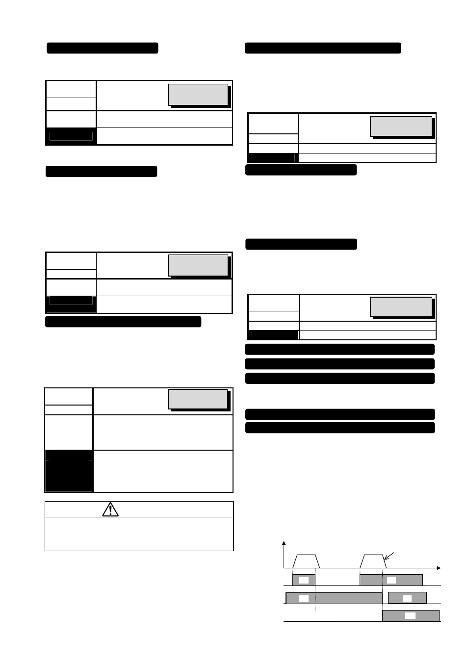
Normally this terminal should be “ON”, when this terminal
goes off during motor running, the motor decelerates to
stop, and outputs alarm “Er6 “. When the inverter is stop
by STOP1/STOP2 signal, the signal should be kept on
4ms or longer.
In case of terminal [STOP2], the deceleration time is
determined by E15( DEC TIME4).
This function is prioritized under any operation (Terminal.
Keypad, Communication...operation). However when the
torque limiter/regeneration avoidance at deceleration is
selected, the time which is set by deceleration time may
be longer.
Inverse mode changeover [IVS]
Interlock signal (52-2) [IL]
Related function
F01, C30
Torque control cancel [Hz/TRQ]
Link enable (RS-485 standard, BUS) [LE]
Universal DI (U-DI)
Pick up start mode [STM]
Related function
H09
Related function
H18
Related function
H30
PG-SY enable ( Option ) [PG/Hz]
Zero speed command with PG option [ZERO]
Pre-exiting command with PG option [EXITE]
ON
Er6
ON
ON
ON
FWD or REV
[STOP1] or
[STOP2]
Alarm
Output
Frequency
In case of [STOP2],
time is fixed by E15
(EDC TIME4)
Forced stop command with Deceleration [STOP1]
Forced stop command with Deceleration time 4 [STOP2]
Related function
F14