Chapter 3: system cable installation, 1 system cable diagram, Figure 3-1 – Adept s350 Cobra User Manual
Page 23
Adept Cobra s350 User's Guide, Rev. D
Page 23 of 94
Chapter 3: System Cable Installation
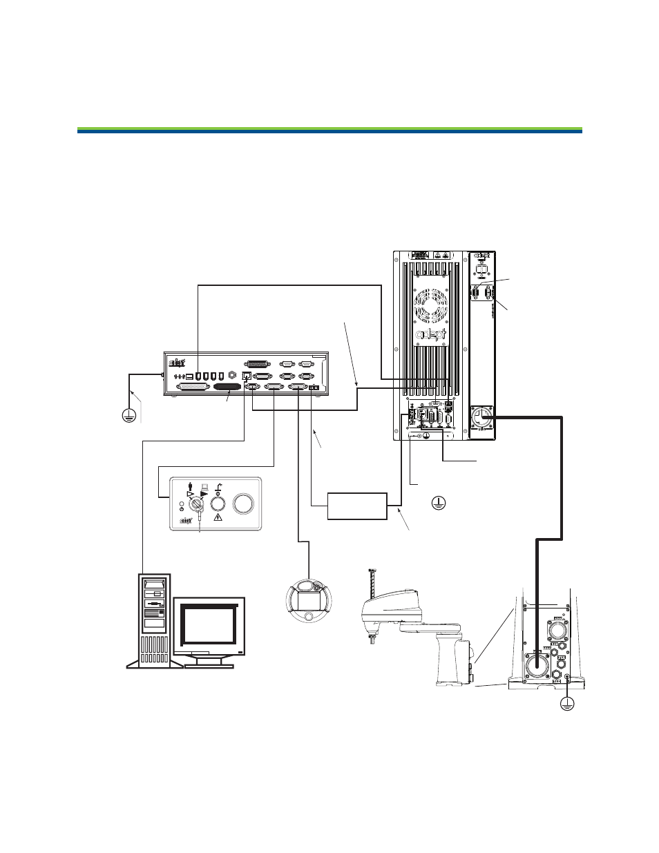
3.1 System Cable Diagram
Ether
net to PC
IEEE 1394 Cable
from Controller SmartServo (Port 1.1)
to MB-40R/MB-eMB40R SmartServo
Adept MB-40R/
eMB-40R
Servo Controller
(MB-40R shown)
Adept
SmartController CX
Adept Cobra
s350 Robot
User-Supplied
Power Supply
Controller (XFP) to
Front Panel (XFP)
Front Panel
Pendant
(optional)
XSYS Cable from Controller to
MB-40R/eMB-40R (XSLV/XSYSTEM)
24 VDC Power from
User-Supplied
Power Supply to
Controller (XDC1)
User-supplied desktop or
Laptop PC Running Adept ACE
Terminator
Installed
User-Supplied Ground Wire
User-Supplied
Ground Wire
External Brake
Connector
Arm Power/
Signal Cable
24 VDC Power from
User-Supplied Power
Supply to MB-40R/
eMB-40R (+24 VDC Input)
User-Supplied
200-240 VAC,
single phase
EXPIO
Connector
Note: Objects are
not drawn to scale.
User-Supplied
Ground Wire
STOP
R
R
ON
SmartServo
IEEE-1394
1 2 3 4
SF
ES
HD
SW1
1.1
1.2
2.1
2.2
OK
1
2
3
XDIO
LAN
HPE
OFF
XSYS
CAMERA
Eth 10/100
XUSR
Device Net
XFP
RS-232/TERM
RS-232-1
XMCP
BELT ENCODER
Smar
tController CX
-+
-+
RS-422/485
XDC1 XDC2
24V
5A
*S/N 3562-XXXXX*
RS-232-2
Figure 3-1. System Cable Diagram for Adept Cobra s350 Robots