Analog voltage gauge type output, Frequency output type gauge – Lingenfelter L460260704 Lingenfelter CAN to Analog Gauge & Relay Output Module CAN2 v1.0 User Manual
Page 26
CAN2-002 Install & Operating Instructions
26
© 2014 Lingenfelter Performance Engineering
Don't connect anything to the CAN2 module wire with the red stripe.
The DIP switch setting on the circuit board for this type of configuration does not control anything
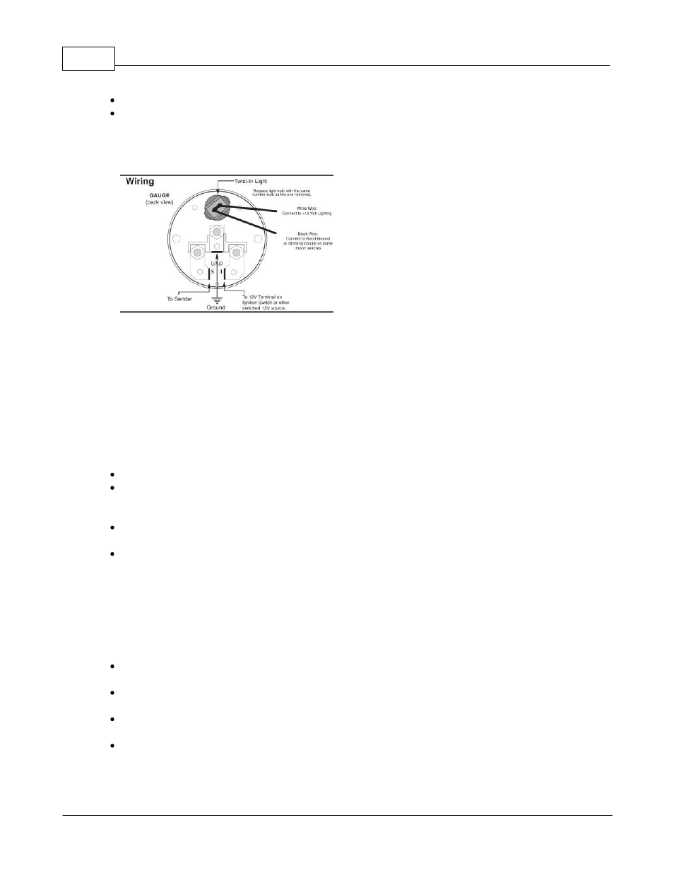
Here is an example rear view of an Autometer short sweep electric gauge used for a single wire
temperature or pressure gauge:
The signal wire (green tracer) from the CAN2 module would connect to the sender (S) connection on the
back of the gauge. The ground would go to a vehicle ground and the +12V terminal would go to a
switched ignition power source.
2.8.2
Analog Voltage Gauge Type Output
This output configuration is used to simulate the sensor output normally found with three wire sensors.
These are often oil, fuel, brake and other pressure sensors.
For an analog voltage signal type gauge you would wire the CAN2-002 module to the gauge as follows:
Make sure the DIP switch on the circuit board is set to External.
Connect the voltage wire from the gauge (that would normally go to the sender) and connect it to the
CAN2-002 module voltage reference wire (wire with a red tracer) for the output channel you are working
on.
Ground from the gauge (that also went to the sender) should be connected to the ground wire (black
tracer) for this output channel on the CAN2 module.
The signal wire (green tracer) on the CAN2 module goes to the signal wire on the gauge.
2.8.3
Frequency Output Type Gauge
This output configuration is usually used to simulate the sensor output normally found with frequency
type sensors. These signal type is usually used with tachometers and speedometers.
For frequency signal type gauge the CAN2 should be wired to the gauge as follows:
Make sure the DIP switch on the circuit board for the output channel you are working on is set to
External
Wire the voltage wire (red tracer) for the output channel in question on the CAN2 to a switched ignition
voltage source.
Connect the ground wire (black tracer) for the output channel in question on the CAN2 to a suitable
ground source.
Connect the signal wire (green tracer) for the output channel in question on the CAN2 to the signal
wire on the gauge.