12 pin connector wires, 5 12 pin connector wires – Lingenfelter L460260704 Lingenfelter CAN to Analog Gauge & Relay Output Module CAN2 v1.0 User Manual
Page 18
CAN2-002 Install & Operating Instructions
18
© 2014 Lingenfelter Performance Engineering
2.5
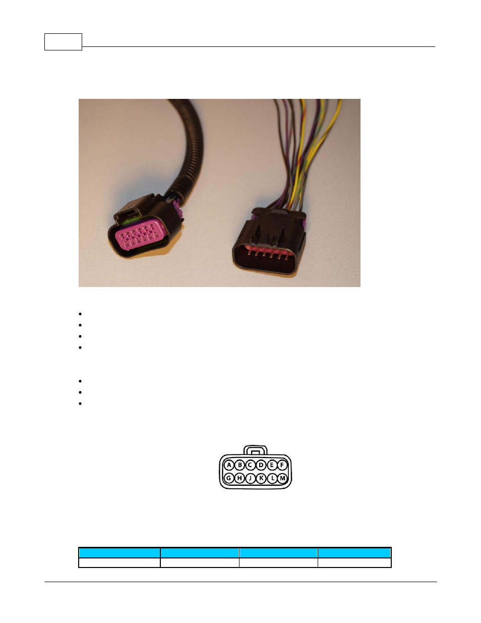
12 Pin Connector Wires
The CAN2-002 has four (4) programmable outputs wired through a 12 pin connector:
Each output channel has its own primary color:
Ch1 – Brown
Ch2 – Grey
Ch3 – Violet
Ch4 – Yellow
Each output channel has three (3) wires of the same primary color with different color tracers:
External voltage reference (+) – Red tracer
Signal output
– Green tracer
Ground reference (–)
– Black tracer
The connector locations are labeled as follows (as viewed from the rear of the female connector on the
CAN2-002 module harness):
Note that in the above 12 pin connector diagram that the letter "i" is skipped so as not to be confused
with a "L" or a "1". The letters for the locations of the 1st and last pin of each row are molded into the
connector but they are very hard to see.
The connector wires are as follows:
Connector cavity
Wire color
Output (Channel) #
Description
A
Brown w red
1
Reference voltage
- L300015297 Lingenfelter LSx Oil Supply Feed Adapter Block v1.2 (2 pages)
- L300025297 Lingenfelter LS1 Oil Cooler Adapter Block v2.7 (2 pages)
- L300046006 Lingenfelter C6 Z06 Corvette High Capacity Oil Tank 2006-2008 v1.0 (14 pages)
- L300080607 Lingenfelter Suburban Yukon Aux Fan Kit AC Clutch Control 2005-07 vE (20 pages)
- L300090607 Lingenfelter Suburban Yukon Aux Fan Kit ECM Fan Control 2005-07 v1.0 (20 pages)
- L300145297 Lingenfelter LS1 LS6 Throttle Body Coolant Bypass Kit v1.1 (4 pages)
- L300152012 Lingenfelter ZL1 Camaro Intercooler Fluid Reservoir 2012 v1.2 (7 pages)
- L300165297 LPE C5 Corvette Supercharger Turbo Intercooler Reservoir Tank v1.2 (6 pages)
- L320030709 Lingenfelter CTS-V Intercooler Radiator Kit 2009-13 v1.1 (39 pages)
- L320061410 Lingenfelter High Capacity Intercooler Heat Exchanger Camaro SS & ZL1 v1.1 (27 pages)
- L330030709 CTSV High Flow Intercooler Pump Upgrade Kit v1.0 (10 pages)
- L350080197 Lingenfelter C5 Corvette Mini Tub Kit (15 pages)
- L350170000 L350180000 LPE Load Cell Shift Knob LNC-TC1 Torque Cut Module v1.1 (4 pages)
- L350191410 Lingenfelter Camaro Shift Knob & Boot Adapter v1.1 (7 pages)
- L350xx0000 Lingenfelter Momo Shift Knob v1.4 (6 pages)
- L360080197 Lingenfelter C5 C6 Corvette Clutch Return Spring Kit v1.1 (14 pages)
- L360091410 Lingenfelter Camaro CTS-V Clutch Return Spring Kit v1.2 (8 pages)
- L380180000 Lingenfelter Differential & Transmission Vent Bladder Kit v1.3 (6 pages)
- L380xx1410 Lingenfelter Camaro Cast 241 MM Aluminum Differential 2010-12 v1.9 (25 pages)
- L450010197 L450020197 Lingenfelter C5 Corvette Battery Relocation v1.5 (22 pages)
- L450080000 Lingenfelter TVS Diode v1.4 (3 pages)
- L450110095 Lingenfelter Diagnostic Port Cover Kit v1.0 (5 pages)
- L460021105 Lingenfelter PWM-001 DTOP Limiter TBSS H3 Hummer v 3.1 (2 pages)
- L460065397 Lingenfelter TRG-002 58x Trigger Conversion Module v1.6 (16 pages)
- L460105297 Lingenfelter LNC-003 Dual RPM Launch Controller v2.7 (18 pages)
- L460111410 Lingenfelter Camaro SS Boost A Pump 2010-2014 v1.2 (18 pages)
- L460135297 Lingenfelter LNC-TC1 Torque Cut Module RPM Limit v1.1 (16 pages)
- L460145297 Lingenfelter LNC-2000 LS Timing Retard Launch Controller v2.0 (32 pages)
- L460160000 Lingenfelter RPM-003 RPM Activated Switch Instructions v1.5 (18 pages)
- L460190108 Lingenfelter CTAP-001 Clutch & Throttle Activation Position Switch v1.7 (10 pages)
- L460145297 Lingenfelter LNC-2001 LS Timing Retard Launch Controller LSA LS9 v1.7 (28 pages)
- L460220000 Lingenfelter TBRC-001 Temperature Based Relay Controller v1.0 (9 pages)
- L460285297 & L460316109 Lingenfelter LNC-TRM Torque Reduction Module v1.2 (20 pages)
- L460330000 Micro Storm MS-001 2-Stage Dual Ramp Progressive Nitrous Controller v 2.6 (14 pages)
- L480330000 SPDT microswitch kit v1.2 (2 pages)
- L460240000 Lingenfelter NCC-002 Nitrous Control Center v1.5 (175 pages)
- L510050197 Lingenfelter C5 C6 Corvette Front Subframe Spacer Kit v1.0 (5 pages)
- L500151410 Lingenfelter - Pedders Camaro SS Coil Over Shocks (21 pages)
- L8200xxxxx Lingenfelter Camaro Billet Pedal 2010-2012 v1.1 (7 pages)
- L820xxxxxx Lingenfelter Cadillac CTS Billet Pedal v1.1 (8 pages)
- L820xxxxxx Lingenfelter C5 C6 Corvette Billet Pedal v1.1 (5 pages)
- L850131410 Camaro Ram Air Hood v 0.8 (13 pages)
- L850141410 Camaro Front Chin Spoiler v0.8 (7 pages)
- L850151410 Camaro Rear Deck Spoiler v0.8 (9 pages)