A1.4 ipb-fpe8ms (theme variation), Figure a1.4 piggyback interface ipb-fpe8ms, Table a1.4 ipb-fpe8ms connector description – Inova High Performance CPU board ICP-PII User Manual
Page 62: Ipb-fpe8, Appendix a
©2001 Inova Computers GmbH
Page A-4
CPU Appendix-A
IPB-FPE8
Appendix A
J10A
J9A
J10B
J9B
J18B
J18A
J11
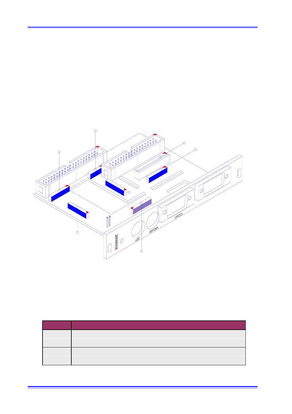
Figure A1.4 Piggyback Interface IPB-FPE8MS
Note that the IPB-FPE8 module does not allow a HD to be connected behind it and the lower 9-
pin D-Sub slot may be used for remote connection of PanelLink for example. The IPB-FPE8MS
shown in figure A1.4 enables connection of floppy, a CD-ROM and other peripherals. The connector
names and descriptions are declared in table A1.4.
Table A1.4 IPB-FPE8MS Connector Description
A1.4 IPB-FPE8MS (Theme Variation)
Figure A1.4 illustrates the construction of the IPB-FPE8MS - a variation of the IPB-FPE8 but with a
number of extra features. The electrical connection to the CPU base board is still via the underside
connector J11 and again, the precautions mentioned for the IPB-FPE8 are valid here.
Connector
Description
J9A, J10A
IDE Primary (Master or Slave)
J9B, J10B
IDE Primary (Master or Slave)*
J11
Mouse, Keyboard and COM1
J18A, J18B
Floppy Disk (either a standard slim-line floppy connector or flex cable)
* If connectors 9a and 10a are configured as Master then 9b and 10b must be Slave.