Finishing, Step 9, Caution – Heat & Glo Fireplace 6000TRS-CE User Manual
Page 32
Heat & Glo • 6000TRS-CE • 2049-900 Rev. R • 3/13
32
!
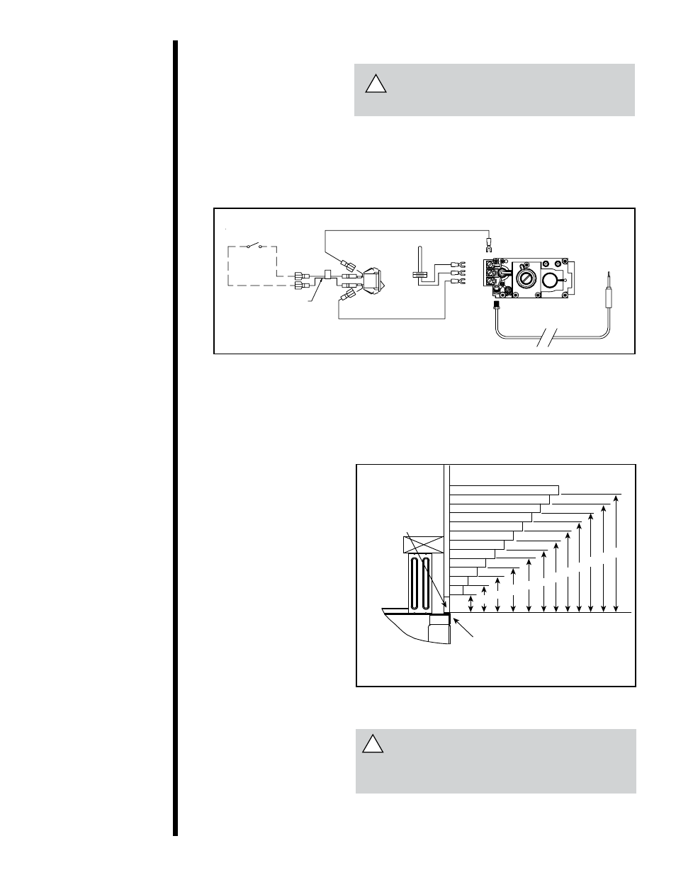
OPTIONAL WALL SWITCH
THERMOSTAT OR REMOTE
REMOTE SWITCH
PIGTAIL
OFF
ON
ON/OFF
SWITCH
THERMOPILE
TP/TH
TP
TH
GAS VALVE
THERMOCOUPLE
!
Figure 29. Standing Pilot Ignition wiring Diagram
wARNING: wHEN FINISHING THE
FIREPLACE, NEVER OBSTRUCT OR
MODIFY THE AIR INLET/OUTLET GRILLES
IN ANY MANNER.
Figure 30. Minimum Vertical and Maximum Horizontal Dimensions
of Combustibles above Fireplace
wARNING: DO NOT CONNECT 230 vAC
TO THE wALL SwITCH OR THE CONTROL
vALvE wILL BE DESTROYED.
label all wires priOr TO DiscONNecTiON
wheN serviciNG cONTrOls. wiriNG errOrs
caN cause imprOper aND DaNGerOus Op-
eraTiON. verify prOper OperaTiON afTer
serviciNG.
cauTiON
Step 9
Finishing
Note: all dimensions are shown in centimeters.
1315,2
1820,3
25,428
5,1
7,6
10,2
13
30,5
28
25,4
23
20,3
18
15,2
TOP FRONT EDGE
OF FIREPLACE
4
2,5
10,211,4
23
NON-COMBUSTIBLE
BOARD
8 9
Note: Factory installed non-combustible board may only be replaced with HHT
product code
SUPERM-60 material and must be fully replaced in its entirety.
The following diagram shows the minimum vertical and
corresponding maximum horizontal dimensions of fire-
place mantels or other combustible projections above the
top front edge of the fireplace. See Figures 2 , 3 and 4 for
other fireplace clearances.
Only non-combustible
materials may be used
to cover the black
fireplace front.