Service adjustment data table, Electrical adjustments – Eiki LC-X71 LC-X71L User Manual
Page 30
- 30 -
0
Thermal Monitor
(Read only)
0
LM76(Temp) A Monitor
-
-
Sensor A for External IC1691
1
LM76(Temp) B Monitor
-
-
Sensor B for Lamp IC1816
2
LM76(Temp) C Monitor
-
-
Sensor C for Panel IC1814
1
Atmosphere Monitor
(Read only)
0
MPXA4114A(Pressure) Monitor
-
-
Atmosphere sensor
1
MPXA4114A(Pressure) Monitor
-
-
Atmosphere sensor [unit: mmHg]
2
MPXA4114A(Pressure) Monitor
-
-
Atmosphere sensor [unit:hpa]
3
Acceleration Monitor
(Read only)
0 MAS1390
(Acceleration)
Monitor
5
FAN Monitor (Read only)
0
FAN A Monitor (PBS)
-
-
Current voltage of Fan (0.01V unit)
1
FAN B Monitor (Lamp-IN)
-
-
Current voltage of Fan (0.01V unit)
2
FAN C Monitor (Lamp-Front)
-
-
Current voltage of Fan (0.01V unit)
3
FAN D Monitor (Power)
-
-
Current voltage of Fan (0.01V unit)
4
FAN E Monitor (Panel)
-
-
Current voltage of Fan (0.01V unit)
5
FAN F Monitor (Exhaust)
-
-
Current voltage of Fan (0.01V unit)
10
RS232C Setting
0
Baurate
0
0 / 1
RS232C baurate (0: 19200 / 1: 9600)
1
Serial mouse switch
0
0 / 1
Serial mouse setting (0: Enable / 1: Disable)
11
PJ-Net Setting
0
Reset Disable
0
0 / 1
PJ-Net Reset (0: Enable / 1: Disable)
20
Logo prohibition
0
Logo prohibition
0
0 / 1
Logo prohibition (0: Menu / 1: Forced)
30
Color Shading/Gamma
0
Color Shading Correction On/Off
0
0 / 1
Color Shading Correction (0: Off / 1: On) Not memorized
1
Gamma Correction On/Off
0
0 / 1
Gamma Correction (0: Off / 1: On) Not memorized
40
Dimmer Control
1
Dimmer Level
15
0 ~ 15
0:250 ~ 15:300W Effect only 300W
2
DIMMER CTRL LEVEL1
7
0 ~ 255
Bright level1 data: Bright level1 when less than the value
3
DIMMER CTRL LEVEL2
14
0 ~ 255
Bright level2 data: Bright level2 when less than the value
4
DIMMER CTRL LEVEL3
21
0 ~ 255
Bright level3 data: Bright level3 when less than the value
5
DIMMER CTRL LEVEL4
28
0 ~ 255
Bright level4 data: Bright level4 when less than the value
6
DIMMER CTRL LEVEL5
35
0 ~ 255
Bright level5 data: Bright level5 when less than the value
7
DIMMER CTRL LEVEL6
42
0 ~ 255
Bright level6 data: Bright level6 when less than the value
8
DIMMER CTRL LEVEL7
49
0 ~ 255
Bright level7 data: Bright level7 when less than the value
9
DIMMER CTRL LEVEL8
56
0 ~ 255
Bright level8 data: Bright level8 when less than the value
10
DIMMER CTRL LEVEL9
63
0 ~ 255
Bright level9 data: Bright level9 when less than the value
11
DIMMER CTRL LEVEL10
70
0 ~ 255
Bright level10 data: Bright level10 when less than the value
12
DIMMER CTRL LEVEL11
77
0 ~ 255
Bright level11 data: Bright level11 when less than the value
13
DIMMER CTRL LEVEL12
84
0 ~ 255
Bright level12 data: Bright level12 when less than the value
14
DIMMER CTRL LEVEL13
91
0 ~ 255
Bright level13 data: Bright level13 when less than the value
15
DIMMER CTRL LEVEL14
98
0 ~ 255
Bright level14 data: Bright level14 when less than the value
16
DIMMER CTRL LEVEL15
105
0 ~ 255
Bright level15 data: Bright level15 when less than the value
17
DIMMER AVE POINT
4
1 ~ 16
Average point data for dimmer 1~16 4
50
Auto-Picture Control
0
Auto-Picture Control Forced OFF
0:follows to Menu, 1:Forced OFF
70
COOLING
0
COOLING_TIME
Cooling time period after power off
1 Not
used
80
Factory use
0
90
PJ Operation History
0
OPERATION_HISTORY_1
0
0 ~ 32767
Operation history in latest operation
~
49
OPERATION_HISTORY_50
0
0 ~ 32767
Operation history in latest 50th operation
50
OPERATION_HISTORY Reset
0
0 ~ 10
It resets the history when the value is changed to 10.
91
PJ Failure History
0
Warning_Log_1
0
0 ~ 32767
Operation history in last operation
~
:
:
49
Warning_Log_50
0
0 ~ 32767
Operation history in last 50th operation
50
Warning_Log Reset
0
0 ~ 10
It resets the history when the value is changed to 10.
112
Lamp Config
0
Lamp Config Change
2500
1000 ~ 8000
Lamp life selection (Step: 500H)
113
Lamp Reset Counter
(Read only)
0
Lamp Reset counter
0
0 ~ 127
Reset times of the lamp time counter
Group No. Adjustment Item
Initial Value
Range
Input source / Description
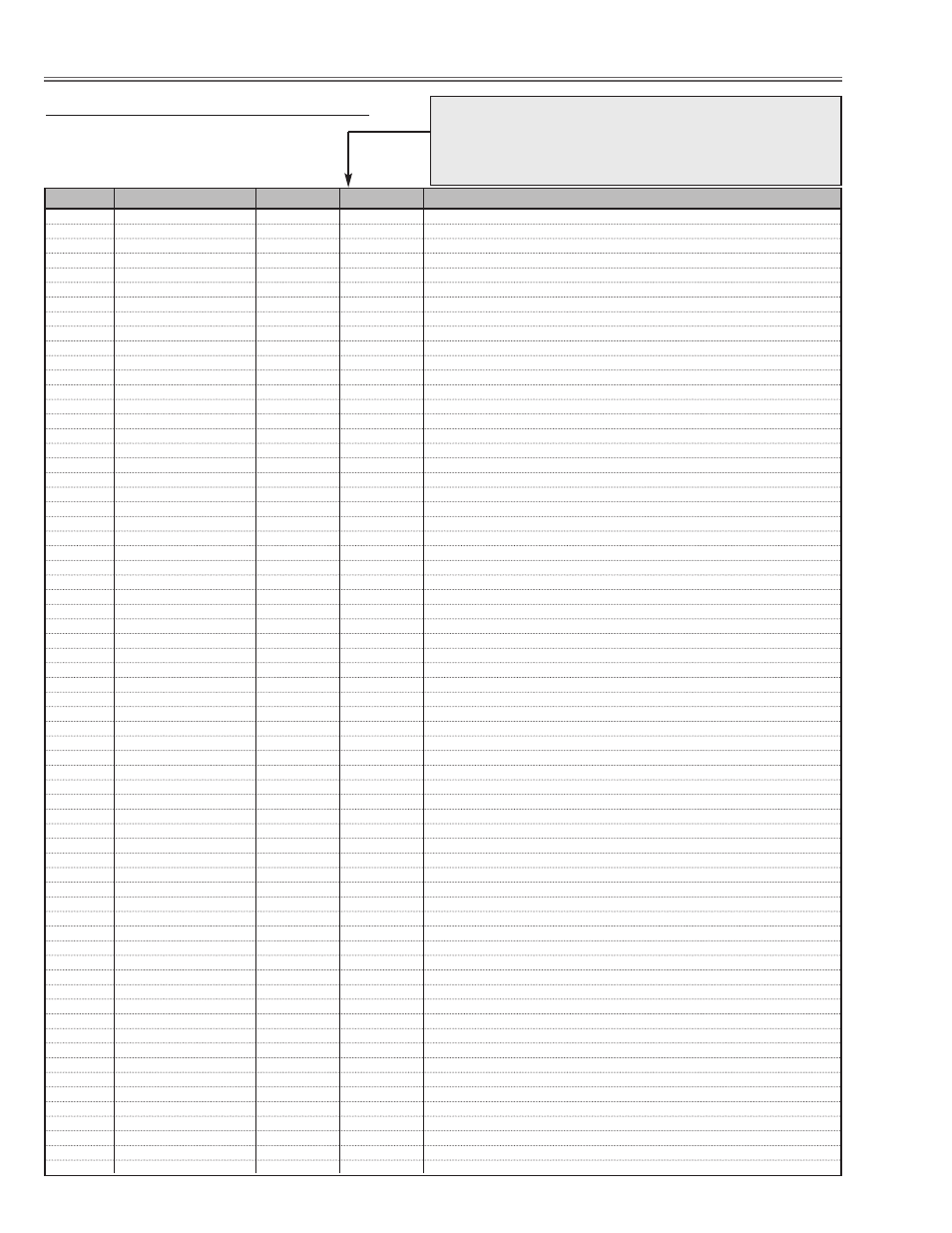
Electrical Adjustments
Service Adjustment Data Table
These initial values are the reference data written from the CPU
ROM to memory IC when replaced new memory IC. The adjust-
ment items indicated with “
✻” are required to readjust following
to the “Electrical adjustments”. Other items should be used with
the initial data value.