ProSoft Technology MVI94-DNP User Manual
Page 92
Reference
MVI94-DNP ♦ Flex I/O
User Manual
DNP 3.0 Server over Ethernet Communication Module
Page 92 of 131
ProSoft Technology, Inc.
December 17, 2010
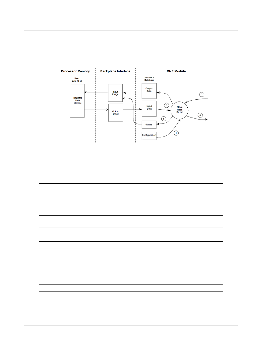
5.4.3 Slave Driver
The Slave Driver Mode allows the MVI94-DNP module to respond to data read
and write commands issued by a master on the DNP network. The following flow
chart and associated table describe the flow of data into and out of the module:
Step
Description
1
The DNP slave port driver receives the configuration information from the Flash data
area in the module. This information configures the serial port and define the slave node
characteristics.
2
A Host device issues read or write commands to the module’s node address. The port
driver qualifies the message before accepting it into the module.
3
After the module accepts the command, the data is immediately transferred to or from
the internal database in the module. If the command is a read command, the data is read
out of the database and a response message is built. If the command is a write
command, the data is written directly into the database and a response message is built.
4
After the data processing has been completed in Step 3, the response is issued to the
originating master node.
5
Counters are available in the Status Block that permit the ladder logic program to
determine the level of activity of the Slave Driver.
The slave driver supports object 110 (octet string data). Four points are pre-
assigned values as defined in the following table.
Point #
Description
0
Module Name as assigned in configuration file.
1
Product Name
2
Version Information in format:
wwww xxxx yyyy zzzz
Where wwww is product code, xxxx is the revision, yyyy is the operating system
number and zzzz is the run number.
3
Manufacturer name for module.
The variation used in the request message determines the length of the string
returned for each point. The maximum string length used by the module is 100.