6 wiring the fault alarm contact – PLANET ICS-2100 User Manual
Page 14
User’s Manual of ICS-210x
-10-
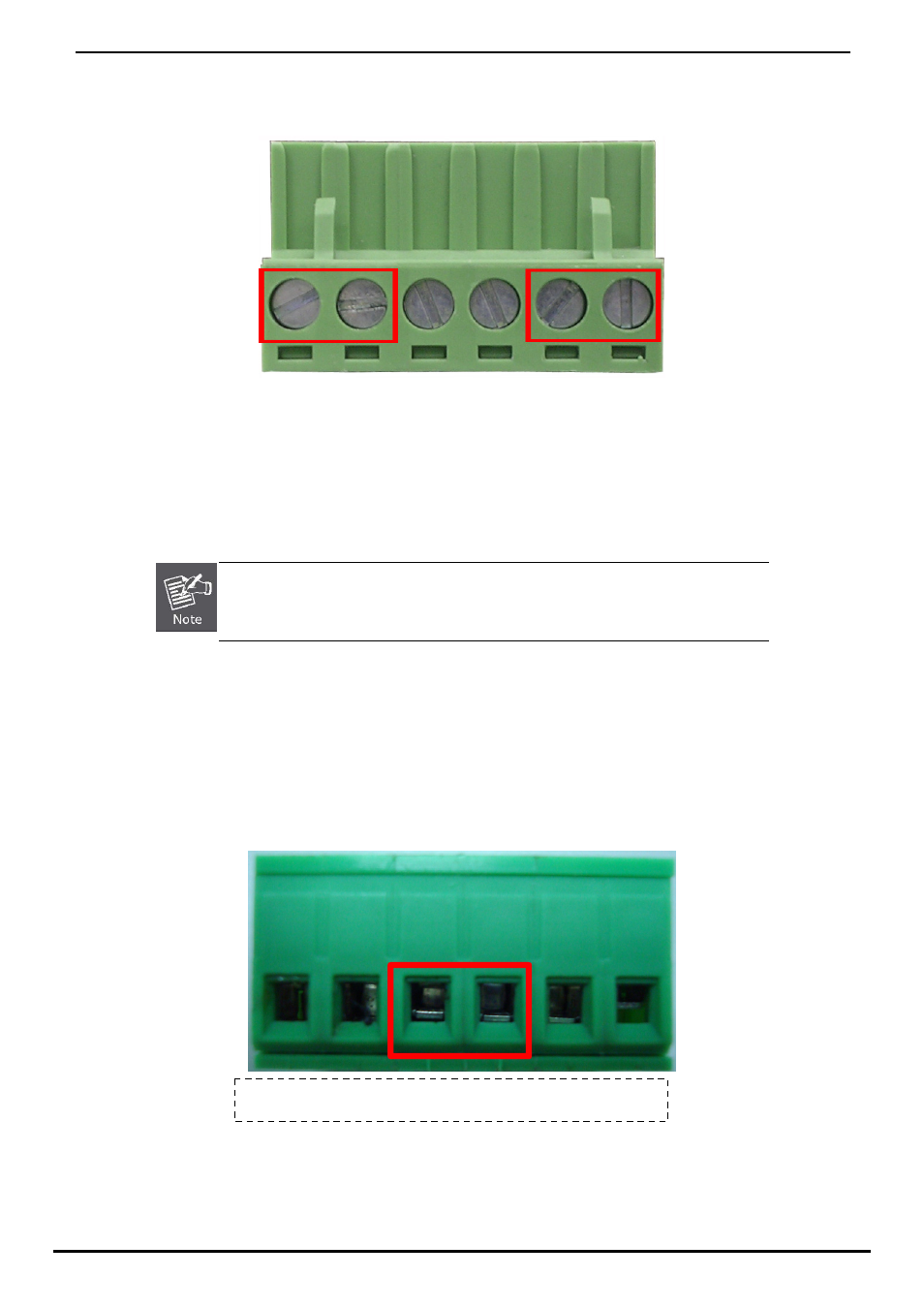
2. Tighten the wire-clamp screws for preventing the wires from loosing. Figure 2-5 shows PWR1 and PWR2 pin of the terminal
block.
1 2 3 4 5 6
Power 1
Fault
Power 2
- + - +
Figure 2-5 PWR1 & PWR2 pin of terminal block.
The wire gauge for the terminal block should be in the range between 12 ~ 24 AWG.
2.1.6 Wiring the Fault Alarm Contact
The fault alarm contacts are in the middle of the terminal block connector as the picture shows below. Inserting the wires, the
Industrial Serial Converter will detect the fault status of the power failure, or port link failure (available for managed model) and
then forms an open circuit. The following illustration shows an application example for wiring the fault alarm contacts. Figure
2-6 shows fault pin of the terminal block & figure 2-7 shows fault alarm contact.
1 2 3 4 5 6
Figure 2-6 Fault pin of terminal block.
Insert the wires into the fault alarm contacts