4 industrial serial converter upper panel, 5 wiring the power inputs – PLANET ICS-2100 User Manual
Page 13
User’s Manual of ICS-210x
-9-
2.1.4 Industrial Serial Converter Upper Panel
The upper panel of the Industrial Serial Converter consist one terminal block connector within two DC power inputs. Figure
2-3 shows the upper panel of the industrial serial converter.
Figure 2-3 Industrial Serial Converter upper Panel.
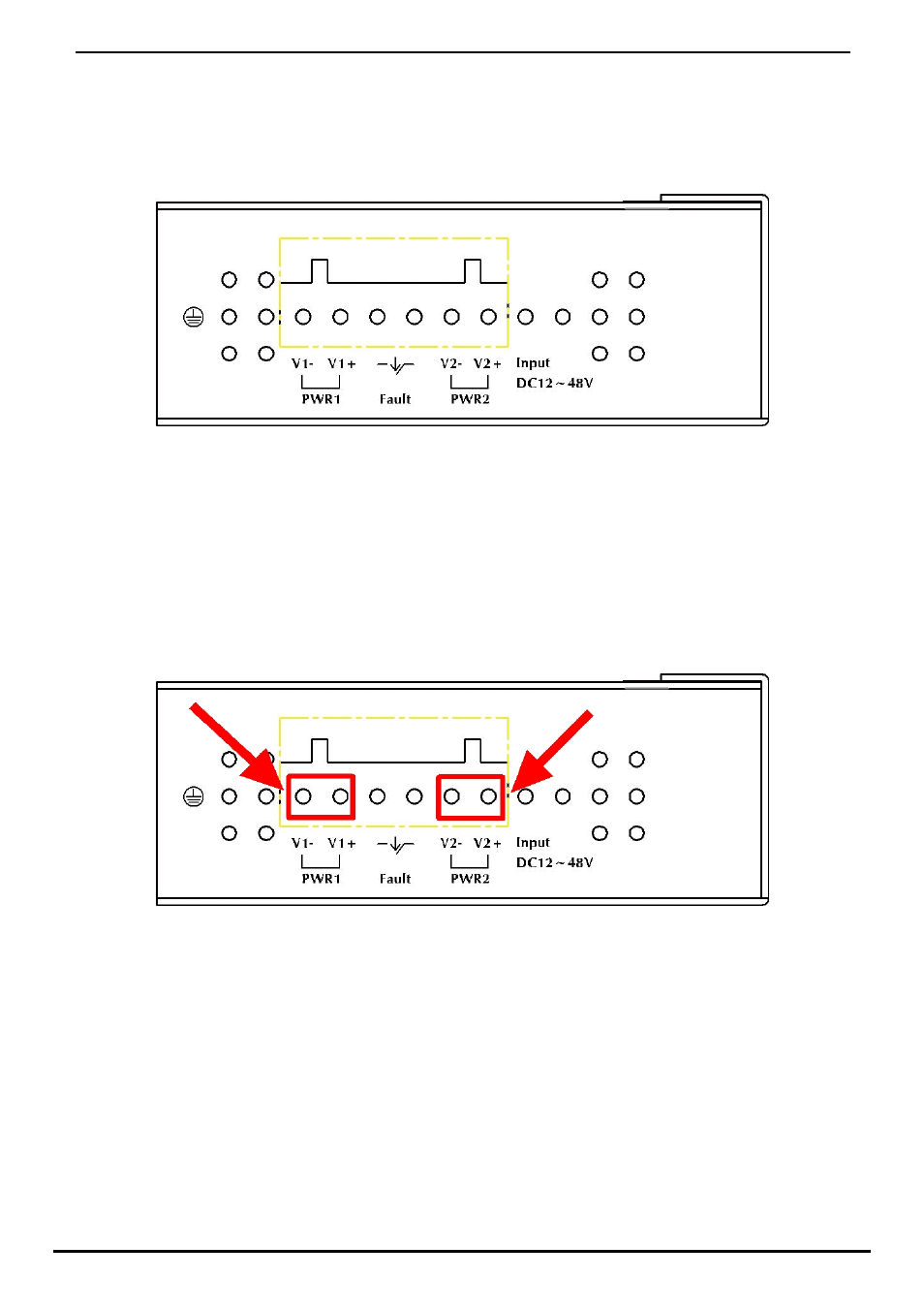
2.1.5 Wiring the Power Inputs
The 6-contact terminal block connector on the top panel of Industrial Serial Converter is used for two DC redundant powers
input. Please follow the steps below to insert the power wire.
1. Insert positive / negative DC power wires into the contacts 1 and 2 for POWER 1, or 5 and 6 for POWER 2. Figure 2-4
shows PWR1 and PWR2 of the industrial serial converter.
V1- V1 + V2 - V2 +
Figure 2-4 PWR1 & PWR2 of Industrial Serial Converter.