PLANET FGSW-2620VM User Manual
Page 27
User’s Manual of FGSW-Series
27
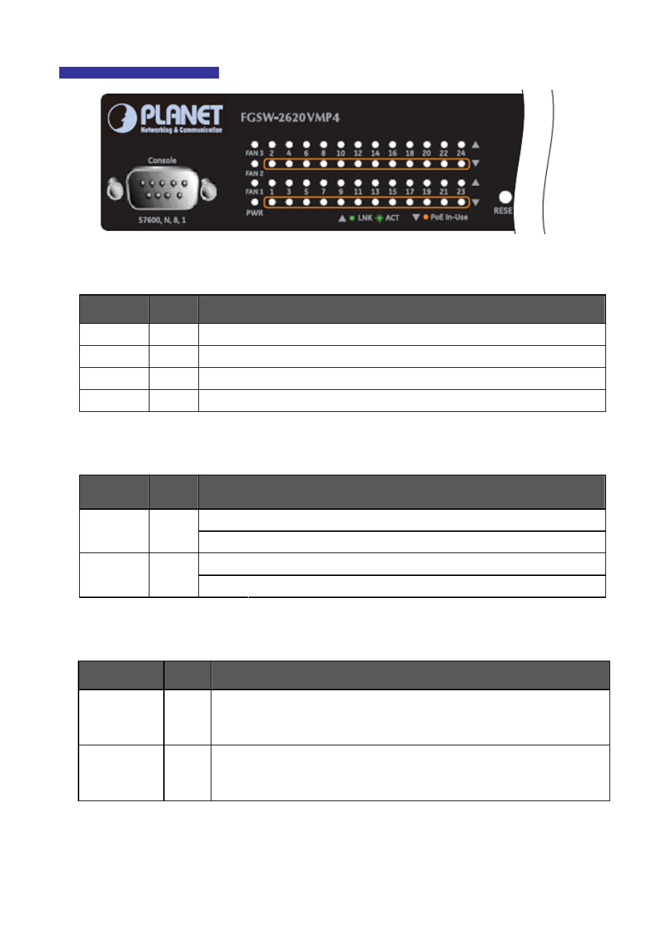
FGSW-2620VMP4 LED indication
Figure 2-1-8:
FGSW-2620VMP4 LED panel
System
LED
Color
Function
PWR
Green
Lights to indicate that the Switch has power.
FAN1
Green
Lights to indicate that the FAN#1 has stopped.
FAN2
Green
Lights to indicate that the FAN#2 has stopped.
FAN3
Green
Lights to indicate that the FAN#3 has stopped.
Per 10/100Base-TX, PoE interfaces (Port-1 to Por-24)
LED
Color
Function
Lights
: To indicate the link through that port is successfully established.
LNK/ACT
Green
Blink:
To indicate that the Switch is actively sending or receiving data over that port.
Lights
: To indicate the port is providing 48VDC in-line power.
PoE In-Use
Orange
Off:
To indicate the connected device is not a PoE Powered Device (PD).
Per 10/100/1000Base-T port /SFP interfaces
LED
Color
Function
LNK/ACT 1000
Green
Lit:
indicate that the port is operating at 1000Mbps.
Off
: indicate that the port is operating at 10Mbps or 100Mbps.
Blink
: indicate that the Switch is actively sending or receiving data over that port.
LNK/ACT 10/100
Green
Lit
: indicate that the port is operating at 10Mbps or 100Mbps.
Off
: indicate that the port is operating at 1000Mbps.
Blink
: indicate that the Switch is actively sending or receiving data over that port.