Installation, 1 hardware description, 1 switch front panel – PLANET FGSW-2620VM User Manual
Page 23
User’s Manual of FGSW-Series
2. INSTALLATION
This section describes the hardware features and installation of the Managed Switch on the desktop or rack mount. For
easier management and control of the Managed Switch, familiarize yourself with its display indicators, and ports. Front
panel illustrations in this chapter display the unit LED indicators. Before connecting any network device to the Managed
Switch, please read this chapter completely.
2.1 Hardware Description
2.1.1 Switch Front Panel
The unit front panel provides a simple interface monitoring the switch.
Figure 2-1-1 to 2-1-5
shows the front panel of the
Managed Switches.
FGSW-2620VM Front Panel
Figure 2-1-1:
FGSW-2620VM front panel
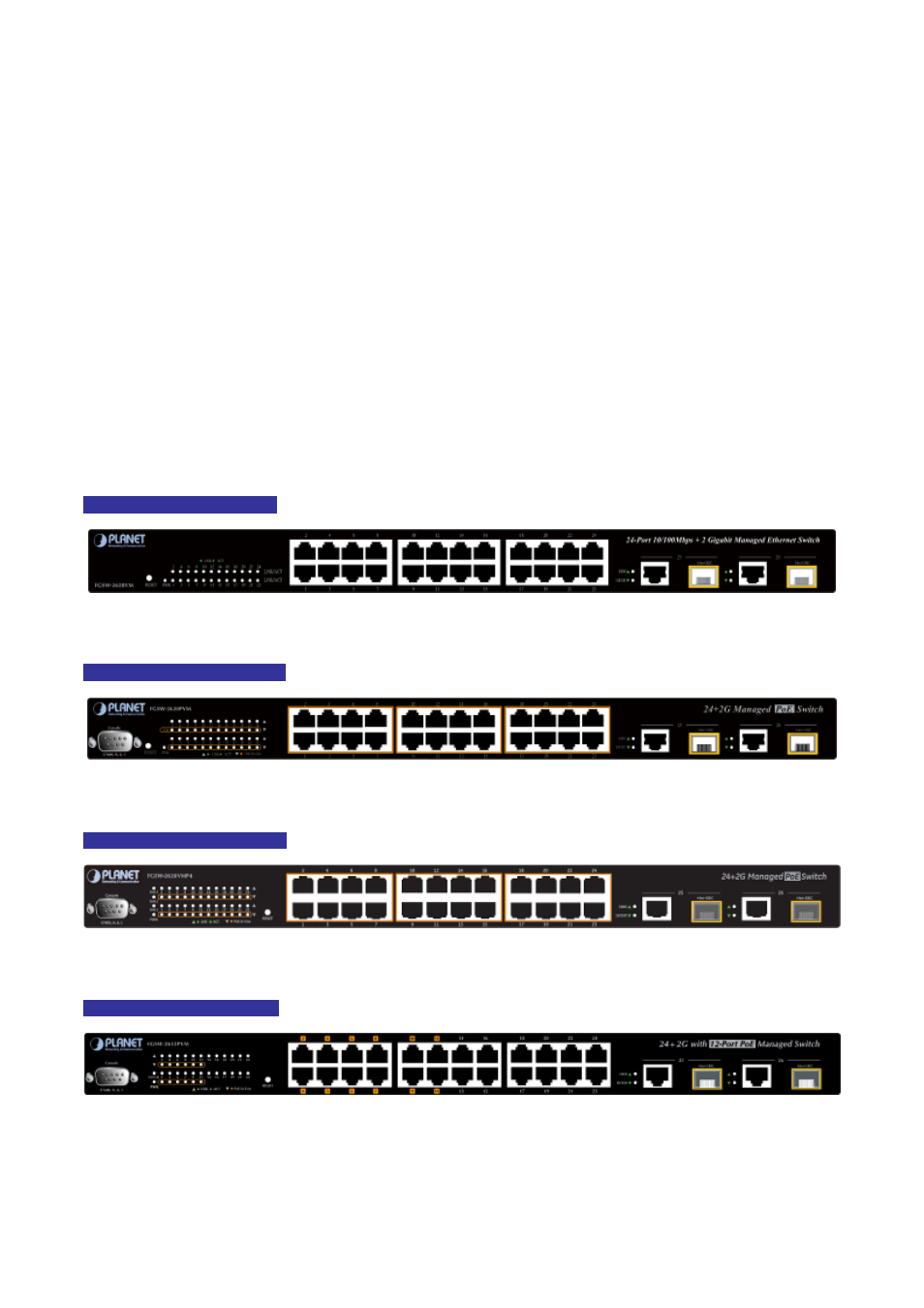
FGSW-2620PVM Front Panel
Figure 2-1-2:
FGSW-2620PVM Switch front panel
FGSW-2620VMP4 Front Panel
Figure 2-1-3:
FGSW-2620VMP4 Switch front panel
FGSW-2612PVM Front Panel
Figure 2-1-4:
FGSW-2612PVM Switch front panel
23