Operating conditions – Avago Technologies LSI53C120 User Manual
Page 39
Electrical Characteristics
3-9
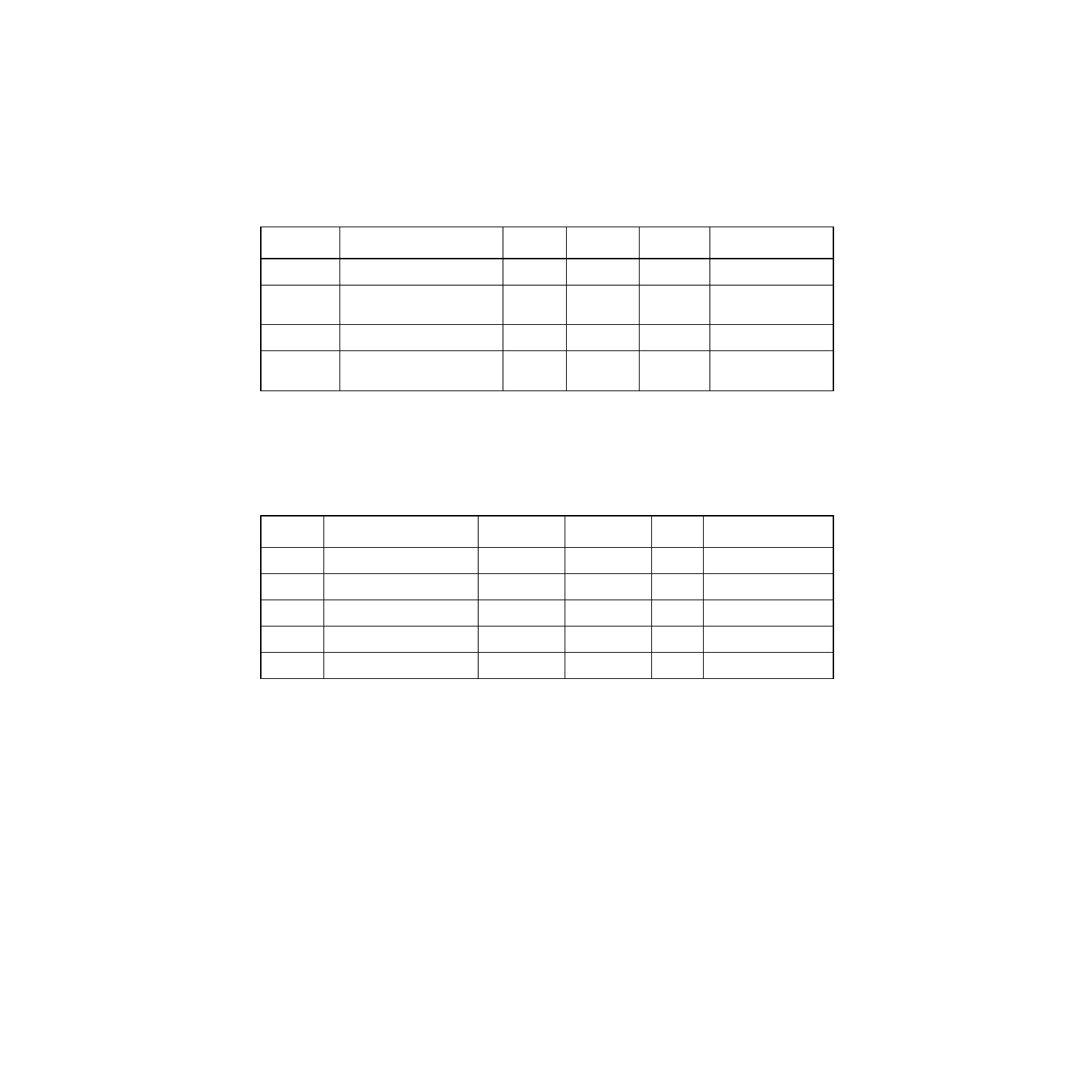
lists the operating conditions for the LSI53C120 device.
provides the minimum and maximum values associated with
these LSI53C120 SCSI signals.
Table 3.9
Operating Conditions
1
Symbol
Parameter
Min
Max
Unit
Test Conditions
V
DD
Supply voltage
4.75
5.25
V
–
I
DD
Supply current (dynamic)
Supply current (static)
–
80
1
mA
mA
–
–
T
A
Operating free air
0
70
°
C
–
θ
JA
Thermal resistance
(junction to ambient air)
–
41.3
°
C/W
–
1. Conditions that exceed the operating limits may cause the device to function incorrectly.
Table 3.10
SCSI Signals – A_SD(15-0)/, A_SDP(1-0)/, A_SREQ/, A_SACK/, B_SD(15-
0)/, B_SDP(1-0)/, B_SREQ/, B_SACK/
Symbol
Parameter
Min
Max
Unit
Test Conditions
V
IH
Input high voltage
1.9
V
DD
+ 0.5
V
–
V
IL
Input low voltage
V
SS
- 0.5
1.0
V
–
V
OH
1
Output high voltage
2.4
3.5
V
2.5 mA
V
OL
Output low voltage
V
SS
0.4
V
48 mA
I
OZ
3-state leakage
-10
10
µ
A
–
1. TolerANT active negation enabled
- MGA-725M4 (4 pages)
- MGA-71543 (4 pages)
- MGA-71543 (3 pages)
- MGA-82563 (6 pages)
- 3ware SAS 9750-8i (48 pages)
- 3ware 9690SA-8I (Channel) (138 pages)
- 3ware 9690SA-8I (Channel) (380 pages)
- 3ware SAS 9750-8i (29 pages)
- 3ware 9550SXU-8LP (Channel) (149 pages)
- 3ware 9550SXU-8LP (Channel) (40 pages)
- 3ware 9650SE-8LPML (Channel) (45 pages)
- 3ware 9690SA-8I (Channel) (27 pages)
- 3ware 9690SA-8I (Channel) (361 pages)
- 6160 SAS Switch (2 pages)
- MegaRAID SAS 9380-8e (43 pages)
- Cache Protection for RAID Controller Cards (139 pages)
- Cache Protection for RAID Controller Cards (13 pages)
- MegaRAID SAS 9271-8iCC (13 pages)
- MegaRAID SAS 9361-8i (13 pages)
- MegaRAID SAS 9266-8i (12 pages)
- MegaRAID SAS 9266-8i (20 pages)
- MegaRAID SAS 9271-8iCC (26 pages)
- MegaRAID SafeStore Software (502 pages)
- MegaRAID SAS 9285-8ecv (80 pages)
- MegaRAID SAS 9285-8ecv (92 pages)
- MegaRAID SAS 0260CV-4i (49 pages)
- MegaRAID SAS 9271-8i (8 pages)
- MegaRAID SAS 0260CV-4i (72 pages)
- MegaRAID SAS 0260CV-4i (64 pages)
- MegaRAID SAS 9361-8i (7 pages)
- MegaRAID SAS 9341-8i (8 pages)
- MegaRAID SAS 9380-4i4e (7 pages)
- MegaRAID SAS 9380-8e (7 pages)
- MegaRAID SAS 0260CV-4i (28 pages)
- MegaRAID SAS 9240-8i (4 pages)
- MegaRAID SAS 9280-24i4e (14 pages)
- MegaRAID SAS 9280-24i4e (16 pages)
- MegaRAID SAS 9260-16i (12 pages)
- MegaRAID SafeStore Software (8 pages)
- MegaRAID SAS 9280-8e (22 pages)
- MegaRAID SAS 9260-8i (4 pages)
- MegaRAID SAS 9261-8i (4 pages)
- MegaRAID SAS 9285-8e (12 pages)
- MegaRAID SAS 9280-16i4e (12 pages)
- MegaRAID SAS 9280-4i4e (4 pages)