KEPCO MST Series User Manual
Page 35
MST SERIES 061813
3-3
grammed in advance of output activation (Standby) or “on-the-fly” (Active) while the output is
enabled; both methods employ a “dry-switching” scheme in order to extend relay life.
For programming polarity reversal in Standby mode, the user simply issues the polarity reversal
command prior to enabling the output; the Power Module will then present reversed output
polarity when enabled.
For polarity reversal while the output is enabled, the action is somewhat more complex although
essentially transparent to the user. Upon receipt of a polarity reversal command, the Power
Module control circuit stores the previous output settings (mode, voltage and current setpoints,
etc.). The output of the Power Module is immediately programmed to zero volts and zero amps.
A time-out delay of 2 seconds maximum is employed to allow for discharge of any load capaci-
tance through the Power Module's return supply; during this time-out interval, the power supply
waits for the output to reach zero volts. When zero volts is established, or at the end of the 2
second time-out, the relays are switched. The output is then reprogrammed to the stored set-
tings and operation continues. During this sequence, error message generation is inhibited.
Restoration of the output to normal polarity follows a similar path.
NOTE: The “return supply” current incorporated into MST Power Modules is limited to a maxi-
mum value which may in some cases be inadequate to fully discharge all external load
capacitance. To ensure dry relay switching for all output conditions, the user must
ensure that the external load capacitance can be discharged completely within the 2
second time-out interval by the available current, or dry switching will not take place.
The maximum external capacitance value that can be discharged within the 2 second
time-out interval is calculated as follows (see Table 3-2):
where C = Maximum external capacitance allowed to maintain dry switching (Farads)
I = Return supply current (Amps)
V = Output voltage (Volts)
T = Time (Sec) = 2 seconds
CAUTION: FAILURE TO OBSERVE THE “DRY SWITCHING” CRITERIA NOTED ABOVE
WILL CAUSE DAMAGE TO THE RELAYS AND VOID THE KEPCO WARRANTY.
In order to allow for settling time, the user should wait approximately 300 milliseconds after
completion of polarity reversal before sending a status query in order to avoid erroneous fault
messages.
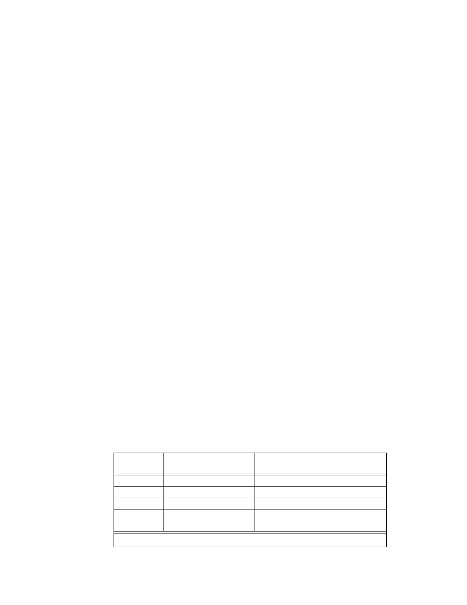
TABLE 3-2. MAXIMUM EXTERNAL CAPACITANCE VALUES TO ENSURE DRY SWITCHING
MODEL
RETURN SUPPLY CURRENT
(MILLIAMPS)
MAXIMUM EXTERNAL CAPACITANCE *
(
µF)
MST 6-20M
400
125,000
MST 15-12M
400
50,000
MST 25-8M
250
20,000
MST 36-5
165
8,800
MST 55-3.5
110
4,000
* Values shown for worst case: T = 2 seconds and
∆
V = maximum voltage.
C
I T
×
V
∆
-----------
≤