Table 2-3. rear terminations, 5 preliminary check-out, 1 required equipment – KEPCO MST Series User Manual
Page 21: 2 initial setup, Preliminary check-out -3, Required equipment -3, Initial setup -3, Rear terminations -3
MST SERIES 061813
2-3
2.5
PRELIMINARY CHECK-OUT
2.5.1
REQUIRED EQUIPMENT
• Host computer w/communication cable for selected controller
• Kepco Controller (See PAR. 1.4.1).
• RA 55 or CA 400 rack adapter; alternative is to use Input Power/Communication Cable
(see Table 1-3)
• Load Interface Cable or mating load connector (see Table 1-3)
• Digital Voltmeter (DVM)
• Switch (SPST) rated 32V d-c, 1A
2.5.2
INITIAL SETUP
Initial set-up is as follows (See Figure 2-3):
1. Connect the Unit under test (UUT) to the computer/controller interface (refer to the appropri-
ate Controller Instruction Manual and to the Rack Adapter (RA 55 or CA 400) Instruction
Manual for source power connections). NOTE: An Alternative configuration using the Input
Power Communication cable in place of the rack adapter may be used.
2. Install the MST Power Module into a vacant rack adapter slot (see PAR. 2.6.2).
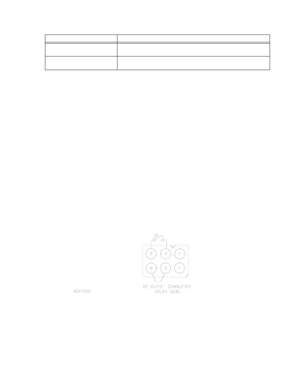
3. Configure the Load Interface Cable as shown in Figure 2-2. If the Load Interface Cable is not
available, wire load mating connector as shown in Figure 2-2.
FIGURE 2-2. DC OUTPUT CONNECTOR CONFIGURATION FOR PRELIMINARY CHECKOUT
CAUTION: DO NOT repeatedly toggle the power ON/OFF switch as this may cause unit to fault.
4. Apply a-c power first to the MST power module(s) by setting Power ON/OFF switch on front
panel to ON., then apply a-c power to the Controller.
5. Set switch S1 (Figure 2-3) to CLOSE SENSE position.
TABLE 2-3. REAR TERMINATIONS
REAR TERMINATION
FUNCTION
AC Input/Control Bus connector
Connects the MST Power Module to single-phase a-c power, safety ground, and two-
wire IEEE 1118 bi-directional Control Bus.
DC output connector
Connects the MST Power Module output lines, sensing lines, frame ground lines and
current share bus to the load.