3 checkout procedure, Checkout procedure -5 – KEPCO MST Series User Manual
Page 23
MST SERIES 061813
2-5
2.5.3
CHECKOUT PROCEDURE
The following checkout procedure requires commands to be issued by the host computer in
order to program the power module or read back information (voltage, current or status) from
the power module; it does not include the IEEE 488 Bus Commands.
NOTE: The following procedure provides specific SCPI and CIIL commands where necessary
to implement the applicable step. These commands are for a Model MST 36-5M Power
Module set to Control Bus Address 1 (the factory default setting); for addresses other
than 1, change commands accordingly (see applicable Controller Instruction Manual
for details).
1. Issue commands from the host computer to initialize the Power Module.
NOTE: Both SCPI and CIIL commands must be issued in the proper syntax; incorrect syntax
can result in the Power Module being “locked out” from accepting further commands. If
this occurs, initialize the power module (see step 1 above). If the “locked out” condition
persists, turn off MST power for approximately 10 seconds, then reapply power. (Refer
to applicable Controller Instruction Manual for details regarding syntax.)
2. Issue commands from the host computer to set the MST Power Module to Voltage Mode,
program output voltage to +E
MAX
, current limit to I
MAX
and enable the output.
NOTE: E
MAX
is the maximum output voltage of the unit listed in Table 1-1; I
MAX
is the maxi-
mum output current of the unit as listed in Table 1-1 for 45° C.
3. Verify that VOLTAGE MODE and OUTPUT ENABLED indicators on front panel are on and
VOLTS meter on front panel indicates E
MAX
.
4. Connect DVM across pins 5 (+) and 2 (–) of the DC Output connector (Figure 2-3) and verify
that DVM reads +E
MAX
.
5. Issue commands from the host computer to read back voltage; verify that readback voltage
is +E
MAX
.
6. Set switch S1 (Figure 2-3) to OPEN SENSE position. Verify that front panel OUTPUT
ENABLED indicator is off, and VOLTS meter reads 0V.
7. Issue commands from the host computer to check Status and verify status reads DEV Load
Path Fault (CIIL) or Relay Error (SCPI); refer to PAR. 3.1.1.
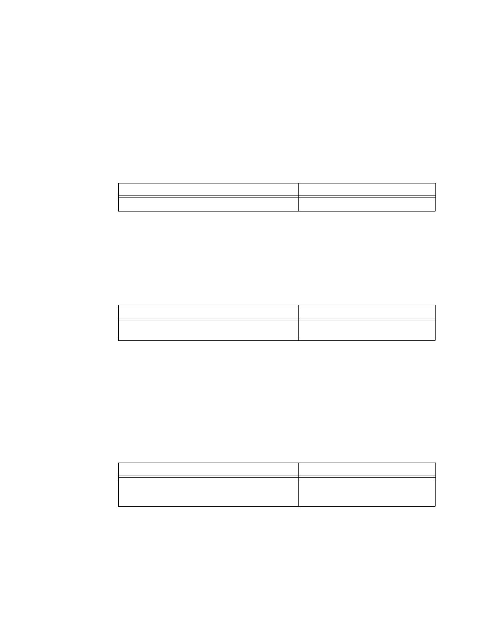
SCPI COMMAND
CIIL COMMAND
*RST
DCL
SCPI COMMANDS
CIIL COMMANDS
FUNC1:MODE VOLT
VOLT1 36; CURR1 5; OUTP ON
FNC DCS :CH1 SET VOLT 36 SET CURL 5
CLS :CH1
SCPI COMMANDS
CIIL COMMANDS
MEAS1:VOLT?
FNC DCS VOLT :CH1
INX VOLT
FTH VOLT