7 parallel configuration, 5 options, 6 accessories – KEPCO MST Series User Manual
Page 17: Table 1-3. accessories, Parallel configuration -7, Options -7, Accessories -7
MST SERIES 061813
1-7/(1-8 Blank)
1.4.7
PARALLEL CONFIGURATION
A parallel configuration may be employed for higher output current and for N + 1 redundant,
“hot-swap” applications. When connected in a parallel configuration, MST Power Modules
employ forced current sharing to ensure equal distribution of the load among all power modules,
improving performance, reducing component stress, and increasing reliability (see PAR. 3.5).
1.5
OPTIONS
The F option (F appended to the Model Number, e.g., MST 6-20MF) incorporates additional fil-
tering to provide significant output noise reduction in the range of 1KHz to 10MHz. Contact
Kepco Sales Engineering for additional information regarding performance and availability.
1.6
ACCESSORIES
The MST Power Module is designed for installation in Kepco Rack Adapter Model RA 55 which
accommodates nine 1/9 rack size power modules. With a 1/9 rack Controller module installed,
the RA55 will accommodate eight 1/9 rack power modules. Connecting cables and IEEE 1118
bus daisy chain terminations are supplied with the RA 55 Rack Adapter. Additional accessories
are listed in Table 1-3.
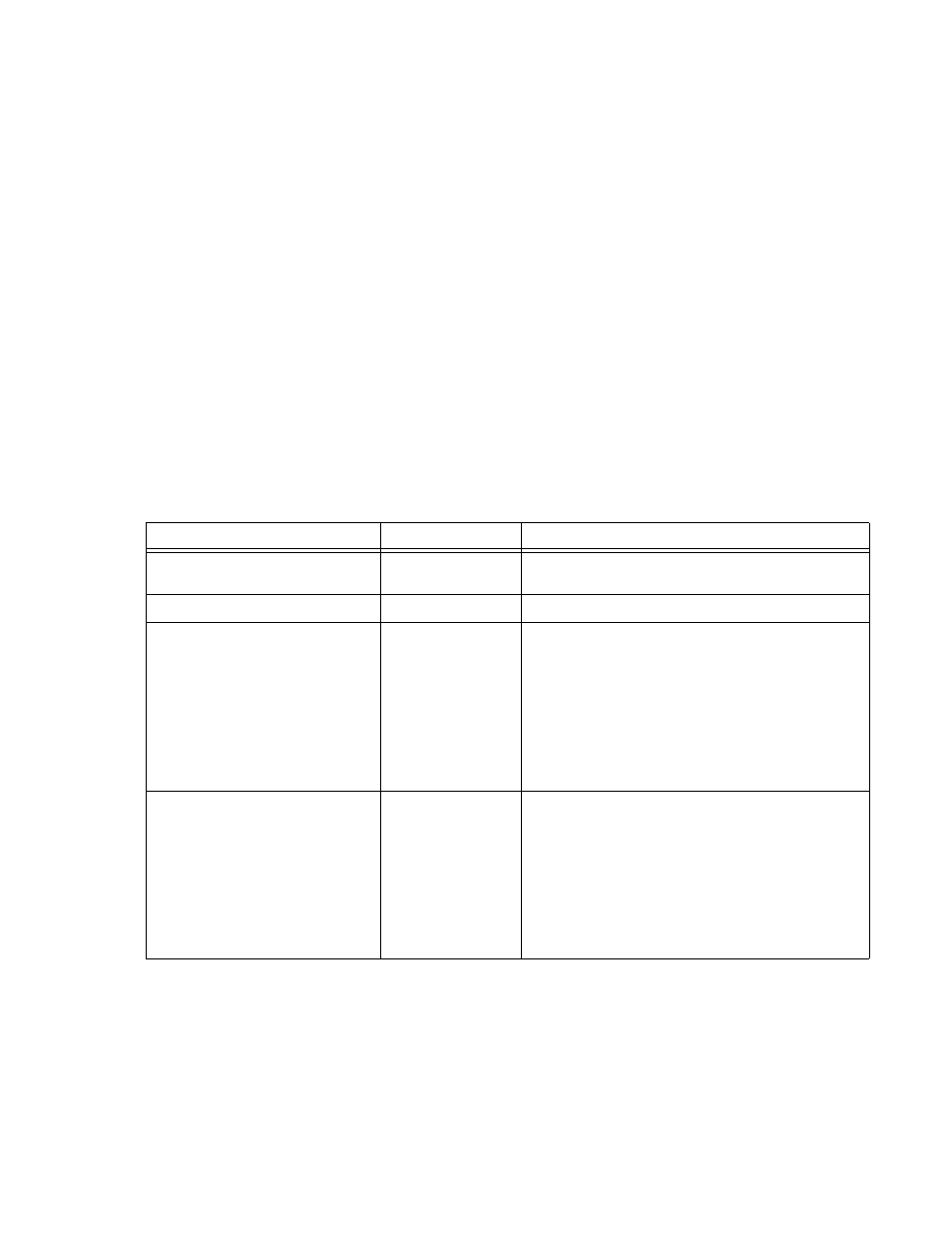
TABLE 1-3. ACCESSORIES
ACCESSORY
PART NUMBER
USE
MATING CONNECTOR
(DC OUTPUT)
142-0372
Mates with DC OUTPUT connector, Kepco P/N 143-0457
(Positronic POW-R-LOK Series 6 pin connector).
LOAD CONNECTOR PINS
107-0327
Replacement pins for DC OUTPUT connector.
LOAD CABLE
118-0849
Allows output load connections of up to 20 Amperes to MST
power module not installed in RA 55 Rack Adapter (for
advanced troubleshooting). Cable length is approximately 7
feet, terminated at one end with mating connector for MST
module output connector. The opposite end is terminated
with two hook lugs for the power connections, as well as a
ring lug for the load sharing connection. Error sensing is
established at the hook lug terminals. This cable is typically
used in conjunction with 118-0850 Input Power/Communica-
tion Cable.
INPUT POWER/COMMUNICATION
CABLE
118-0850
Allows power and communication connections to MST
power module not installed in RA 55 Rack Adapter (for
advanced troubleshooting). Cable length is approximately 7
feet, terminated at one end with mating connector for MST
module a-c input/control bus connector. The opposite end of
the cable is split into two terminations, one a NEMA 5-20P
a-c mains plug and the other a 9-pin D-sub connector that
mates with the control bus connector of RA 55 (as well as
CA 400, MST 488-27 or TMA 4882-27). This cable is typi-
cally used in conjunction with 118-0849 Output Load Cable.