2 load connection with remote error sensing, Load connection with remote error sensing -13, Connector locations and pin assignments -13 – KEPCO MST Series User Manual
Page 31: Figure 2-6 and t, E 2-6)
MST SERIES 061813
2-13/(2-14 Blank)
2.9.2
LOAD CONNECTION WITH REMOTE ERROR SENSING
If the load is located at a distance from the power supply terminals, or if reactive and/or modu-
lated loads are present, remote error sensing should be used to minimize their effect on the volt-
age stabilization. A twisted shielded pair of wires from the sensing terminals directly to the load
will compensate for voltage drops in the load interconnection scheme (up to 0.5V maximum per
wire); the termination point of the error sensing leads should be at or as close as practical to the
load. For these conditions it is also recommended that some amount of local decoupling capac-
itance be placed at the error sense termination point to minimize the risk of unwanted pick-up
affecting the remote error sense function. For very long power module/load interconnecting
cables and/or reactive loads, it may be necessary to add decoupling capacitors between the
power and sense terminals at the power module side of the cable to suppress oscillation due to
cable inductance. A general recommendation is to install a network of one (1) 10µF, 6.3V capac-
itor paralleled by one (1) 0.1µF ceramic capacitor across each output sense pair (pins 6 to 5 and
3 to 2, respectively).
NOTE: As electrolytic capacitors are normally polarized make sure that the positive (+) terminal
of each one are respectively connected to the +V (pin 6) and -S (pin 2) pins.
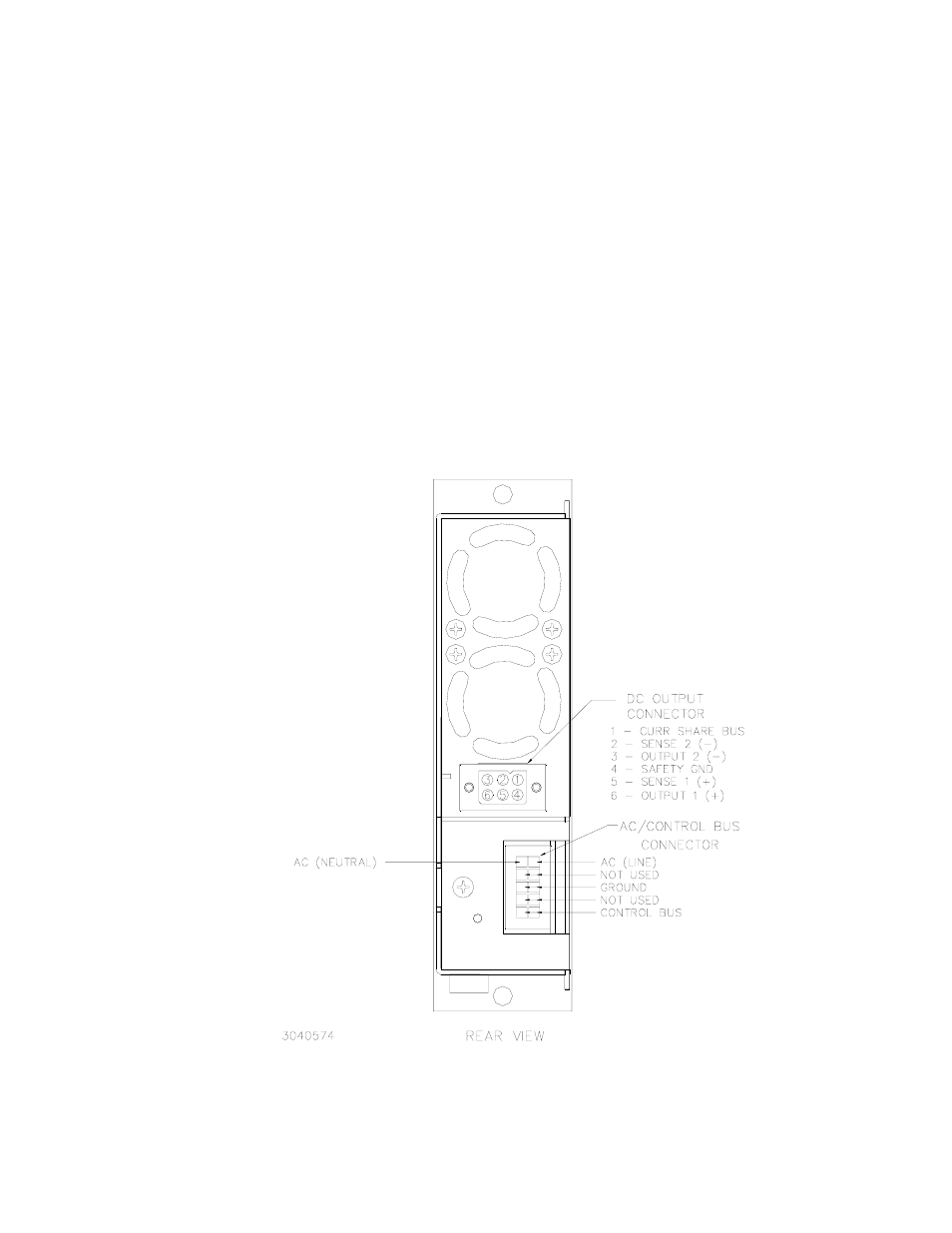
FIGURE 2-6. CONNECTOR LOCATIONS AND PIN ASSIGNMENTS