4 features, 1 control/programming, Features -3 – KEPCO MST Series User Manual
Page 13: Control/programming -3
MST SERIES 061813
1-3
1.4
FEATURES
1.4.1
CONTROL/PROGRAMMING
Control of the MST Power Module is via the IEEE 1118 2-wire serial bus operating at 375KHz;
as many as 27 separate modules of either the MST, MAT, MBT or BOP Series design can be
addressed via the bus (see Figure 1-3). Decoders for RS232, IEEE-488 and VXI are available in
modular form and stand-alone types. As shown in Figure 1-3, the following controllers are avail-
able to control of MST (and MAT) Power Modules directly from a computer.
a. Controller Model TMA PC-27 plugs into a half-card slot of a DOS-based PC and allows key-
board control of the MST via the IEEE 1118 bus.
b. Controller Model TMA 4882-27 is free-standing and allows host computers designed for
RS232 or IEEE 488 bus communication to control the MST via the IEEE 1118 bus.
c. Controller Model TMA-VXI-27 plugs into a slot in a VXI chassis and allows VXI-based com-
puters to control the MST via the IEEE 1118 bus.
d. Controller Model MST 488-27 plugs into a slot in a Model RA 55 Rack Adapter and allows
host computers designed for RS232 or IEEE 488 bus communication to control the MST via
the IEEE 1118 bus.
e. The MST Power Module can also be directly controlled via the keypad of the MBT Series
(“G” Option) Power Supply via the IEEE 1118 bus.
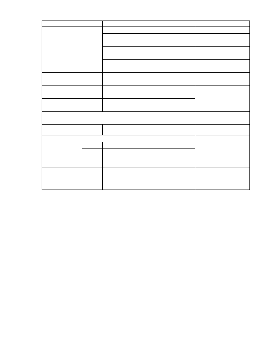
Status Indicators
Voltage Mode
Green LED
Current Mode
Amber LED
Current Share
Amber LED
Output Enabled
Green LED
Polarity Reversed
Green LED
Output Fault
Red LED
Output Enable
Built in power and sense relay
Polarity Reversal
Built in power and sense relay
Parallel Connection
N+1 redundancy, forced current share
Currents divided equally
Overvoltage protection
Tracks output setting, power shutdown
Latched, reset
by cycling source
power off
Overtemperature
Thermostat
Open sense wire
Automatic detection with power shutdown
Backup current limit
Tracks output current at 110%
PHYSICAL
Type of Construction
Enclosed, plug-in style includes status LEDs, two digital
meters, handle and ON/OFF switch
Cooling
Internal D-C Cooling Fans
Exhaust to rear
Module
Dimensions
English
7” x 1.83” x 20”
Refer to Figure 1-2
Metric
178 x 46.5 x 508 mm
Weight
English
8 lbs.
Metric
3.6 Kg.
Load Connection
Mates with Positronic POW-R-LOK Series 6 pin connec-
tor, Kepco P/N 143-0458 (See Figure 2-6 and Table 2-5),
Mating connectors provided with
MST compatible rack adapters
Source Connection
Mates with Molex Minifit, Jr. Series 10 pin connector,
Kepco p/n 143-0544 (See Figure 2-6)
Mates with a-c backplane in
MST compatible rack adapters
TABLE 1-2. MST GENERAL SPECIFICATIONS (CONTINUED)
SPECIFICATIONS
RATING/DESCRIPTION
CONDITION