RIGOL DM3068 User Manual
Page 148
RIGOL
User’s Guide for DM3068
6-2
100.0000 MΩ
200 nA || 10 MΩ
0.300 + 0.010
0.800 + 0.010
0.800 + 0.010
0.1500 + 0.0002
Diode Test
2.0000 V
[7]
1 mA
0.002 + 0.010
0.008 + 0.020
0.010 + 0.020
0.0010 + 0.0020
Continuity Test
2000.0 Ω
1 mA
0.002 + 0.010
0.008 + 0.020
0.010 + 0.020
0.0010 + 0.0020
[1]
Specifications are for 90-minute warm-up and 100 PLC integration time. When the integration time is <100 PLC, add the appropriate “RMS Noise
Adder” listed in the following table.
[2]
10% overrange on all ranges except DCV 1000 V and DCI 10 A ranges.
[3]
Relative to calibration standards.
[4]
For each additional volt over ± 500 V, add 0.03 mV error.
[5]
For continuous current > 7A DC or 7A AC rms, 30 seconds ON and 30 seconds OFF.
[6]
Specifications are for 4–wire resistance measurement or 2–wire resistance measurement using REL operation. Without REL operation, add 0.2 Ω
additional error in 2-wire resistance measurement.
[7]
Accuracy specifications for the voltage measured at the input terminal only. 1 mA test current is typical. Variation in the current source will cause some
variation in the voltage drop across a diode junction.
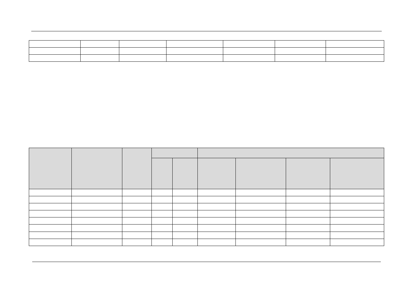
Performance of Different Integration Time – 50 Hz (60 Hz) Power-line Frequency
Integration
Time
Number of
Power Line
Cycles
(NPLC)
Resolution
[1]
(ppm Range)
NMRR
[2]
(dB)
Readings/s
[3]
RMS Noise Adder
[4]
(% of Range)
50 Hz
60 Hz
DCV 20 V
DCV 2 V
200 V
Resistance 2 kΩ
20 kΩ
DCV 1000 V
DCI 2 mA
200 mA
DCV 200 mV
Resistance 200 Ω
DCI 10 A
0.006
2.7
0
10000 10000
0.0006
0.0007
0.0015
0.0040
0.02
1.6
0
2500
3000
0.0004
0.0004
0.0008
0.0025
0.06
1
0
833
1000
0.0003
0.0003
0.0006
0.0025
0.2
0.5
0
250
300
0.0001
0.0002
0.0003
0.0015
1
0.22
60
50
60
0
0.0001
0.0002
0.0004
2
0.17
60
25
30
0
0
0.0001
0.0003
10
0.08
60
5
6
0
0
0
0.0002
100
0.035
60
0.5
0.6
0
0
0
0