MCZ Club AIR User Manual
Page 26
PELLET STOVES
Chapter 3
INSTALLATION AND USE MANUAL
page
26
Installation and assembly
Technical service - Rights reserved MCZ Group S.p.A. - Reproduction prohibited
In case of crossing walls built of flammable material, THE INSTALLER
MUST suitably insulate the pipe of the stove that crosses the walls,
using suitable insulating material (1.3-5 thick with a min. thermal
conductivity of 0.07 W/m°K).
A pipe which is inserted in the wall must be properly insulated so that it
does not lose heat and so that air outlet is silent.
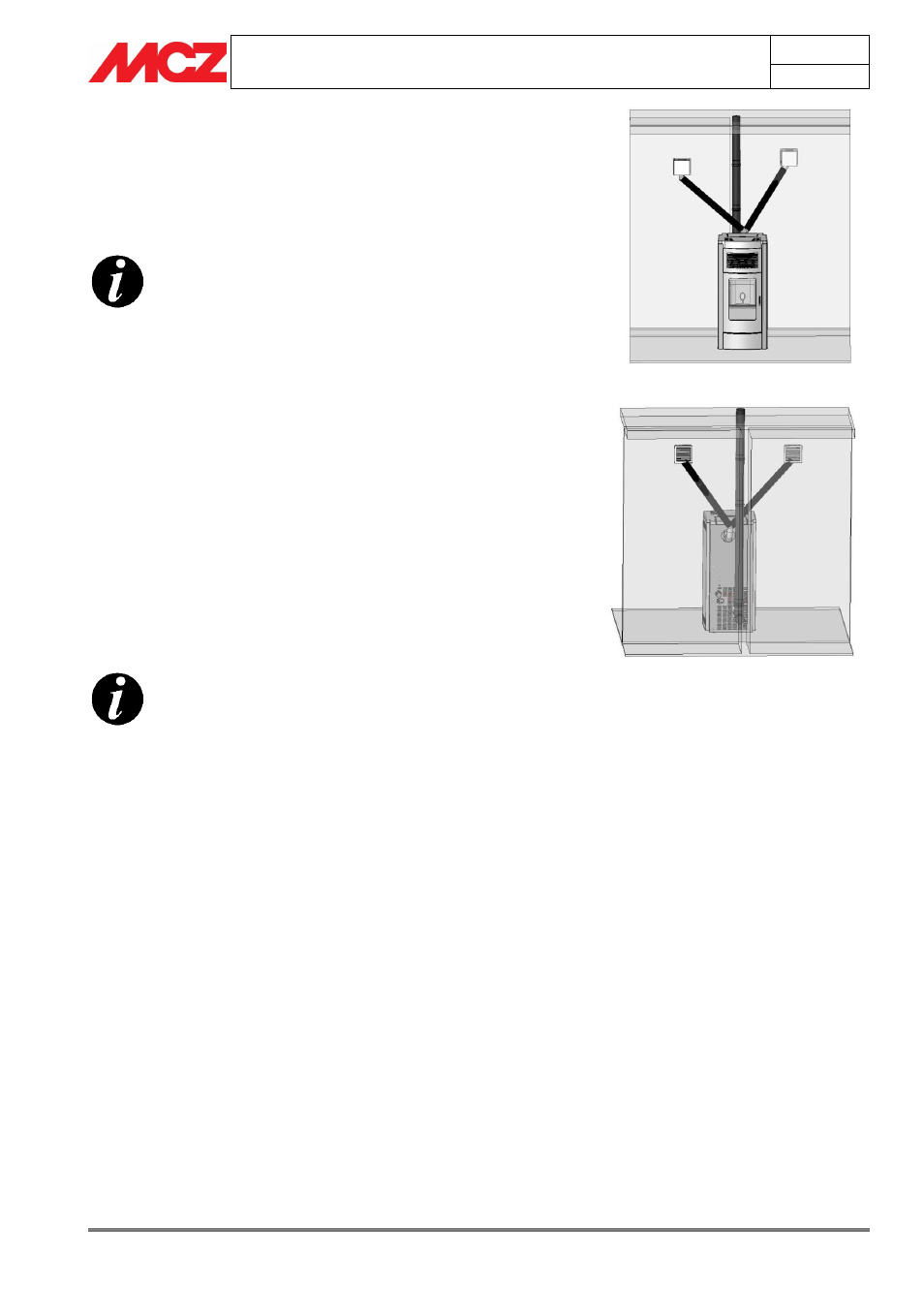
You should use ducts of the same length so that the
air is evenly distributed. Otherwise, the air will tend
to flow through the shortest or least twisted ducts
In the example in figures 6 and 7 (front and rear view) the air duct is
an equal length totaling 8 meters, or in other words the pipes (B) will
have a length of approximately 4 meters each. In the case of ducts with
different lengths, the total must always be maximum 8 meters (example
3 + 5 meters). In this case the heat will spread through the rooms in an
uneven manner.
The recirculation of air in the room occurs using the perforated sheet
metal placed in the rear of the stove C and the holes placed on the
metal sheet bottom
It is possible to choose the volume of air you wish to discharge from the
front part and from the rear part of the stove in an independent
manner, by adjusting the ventilation power directly with the remote
control.
3.4. INSTALLATION OF CERAMIC CLADDING FOR
SUITE AND CLUB
It is advisable to place small felt pads on the
ceramics where these touch the metallic parts of the
stove structure and in the contact between the
ceramic.
3.4.1.
Assembly of the lower panel – Suite and Club Stoves
The stove is delivered with all the ceramics packed. Therefore, before
assembling the side tiles and the top, it is necessary to insert the lower
panel.
Proceed in the following way (fig.8):
Remove the micro-perforated sheet metal grill B on the right
side (handle side) on the upper part by removing the two
screws C.
Remove the screw D on the sheet metal E in a way that the
profile A is no longer locked.
At this point slightly lift the sheet metal E and remove the
profile A.
To remove the profile A lift it (sliding it from the base) and tilt
it slightly in a way that the plugs inserted on the base come
out.
Take the lower panel F and insert it from the right (handle
side) towards the left in a way that it enters exactly in the
housings
Reinsert the profile A making the plugs enter the case, and
lift the sheet metal E in a way to realign the profile “A”. Work
in a way that the upper plugs of the profile “A” are inserted in
the housings of the sheet metal “E”.
Figure 6 – Front view of air outlet system
Figure 7 – Rear view of air outlet system
A
B
B
B
B
A