Installation – Magnum Energy RD Series User Manual
Page 35
©
2010 Magnum Energy, Inc
Page 29
Installation
2.6.1
Sizing the Grounding Electrode Conductors
AC Side - The size of the AC Grounding Electrode Conductor (GEC –AC) depends on the size of
the largest ungrounded conductor feeding the AC load center. One #8 AWG (8.4 mm
2
) copper
conductor will serve as an AC Grounding Electrode Conductor (GEC –AC) for AC power conductors
smaller than and including #2 AWG (33.6 mm
2
) copper. See
Table 2-4 for additional values.
Table 2-4, AC Grounding Electrode Conductor Sizing
Size of Largest Ungrounded
Conductor
Minimum Size of Grounding
Electrode Conductor
#2 AWG or smaller
#8 AWG
(8.4 mm
2
)
#1 to #1/0 AWG
#6 AWG
(13.3 mm
2
)
#2/0 or #3/0 AWG
#4 AWG
(21.1 mm
2
)
Over #3/0 AWG
through 350 kcmil
#2 AWG
(33.6 mm
2
)
DC Side - To size the DC grounding electrode conductor, you must fi rst determine which one of the
following three methods will be used to connect the DC and AC grounding points in the inverter’s
two electrical systems to the common “earth” ground:
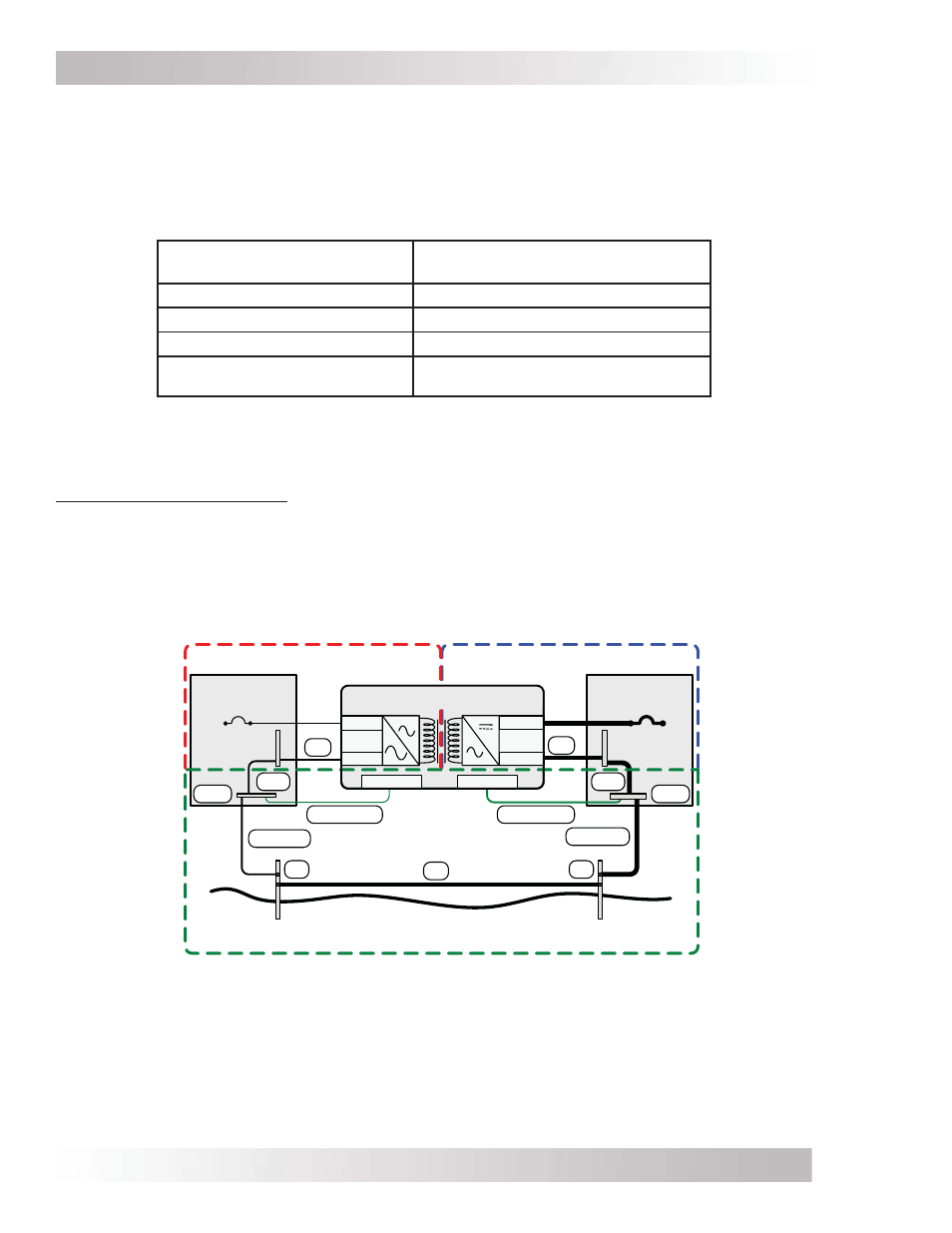
Method 1 (see Figure 2-16): This method uses a separate grounding electrode for the DC system
and the AC system. In this method — since there are multiple connections to the DC Grounding
Electrode (GEC – DC) — the size of the DC grounding electrode conductor cannot be smaller than
the largest conductor in the DC system (usually the battery-to-inverter cable).
The DC Grounding Electrode (GE – DC) must be bonded to the AC Grounding Electrode (GE – AC)
to make a grounding electrode system; this bonding conductor (BC) cannot be smaller than the
largest grounding electrode conductor, either AC or DC.
A C
D C S e rvice
P a n e l
A C S e rvice
P a n e l
D C E lec tric al S y s tem
A C E lec tric al S y s tem
N eutral
Positive
N egative
D C
G rounding
S y s tem
N e g a tive
S B J
GC
GE C -A C
E GC - A C
AC Ground
D C Ground
S B J
E GC - D C
GC
N e u tra l
H ot
GE C -D C
GE
GE
GB B
GB B
Grounding Electrode
(D C side dedicated)
Grounding Electrode
(AC side dedicated )
R D S e rie s In ve rte r/C h a rg e r
B C
Figure
2-16, Multiple Connections to DC Ground Rod (Method 1)