Installation, 2 mounting the inverter, Figure 2-2, approved mounting positions – Magnum Energy RD Series User Manual
Page 16
Page 10
©
2010 Magnum Energy, Inc.
Installation
Accessible - Do not block access to the inverter’s remote control and accessory ports, as well
as the inverter’s controls and status indicator. Also allow enough room to access the AC and DC
wiring terminals and connections, as they will need to be checked and tightened periodically. See
Figure 2-3 for the RD Series’ inverter/charger dimensions.
Away from sensitive electronic equipment - High-powered inverters can generate levels of RFI
(Radio Frequency Interference). Locate any electronic equipment susceptible to radio frequency
and electromagnetic interference as far away from the inverter as possible.
2.2 Mounting the Inverter
The inverter base can reach a temperature up to 90°C (194°F) and it is recommended that it should
be mounted on a non-combustible surface*. This surface and the mounting hardware must also be
capable of supporting at least twice the weight of the inverter. To meet regulatory requirements,
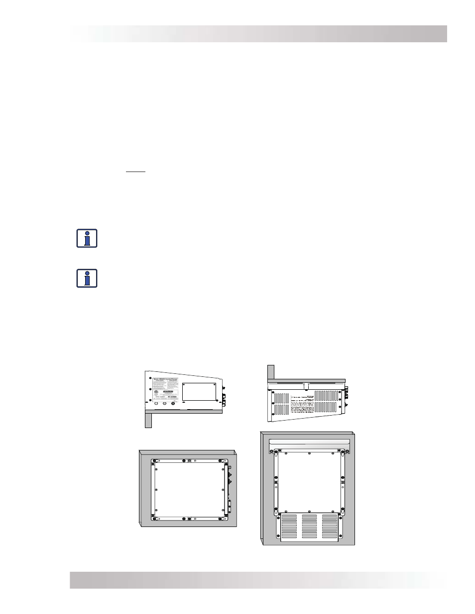
the RD Series must be mounted in one of the following positions, as shown in Figure 2-2:
above or under a horizontal surface (shelf or table)
or, on a vertical surface (wall) with the DC terminals to the right
or, on a vertical surface (wall) with DC terminals toward the bottom, MP-HOOD (inverter hood)
installed on the top, and either the ME-CB (Conduit Box) or MMP Series (single inverter) enclosure
installed on the inverter’s bottom.
Info: The ME-CB and the MMP Series enclosure prevent material from falling out the
bottom in the event of an internal fi re, and also allow suffi cient ventilation to prevent the
inverter from overheating under normal operating conditions. The MP-HOOD inverter
hood helps prevent items from falling inside, causing damage to the inverter.
Info: Magnum provides a backplate with a suitable surface for mounting the
inverter. These backplates also provide the ability to mount the MMP Series enclosure
(PN: BP-MMP).
After determining the mounting position, refer to the physical dimensions as shown in Figure 2-3,
or use the base of the inverter as a template to mark your mounting screw locations.
* Non-combustible surface - A surface made of material that will not ignite, burn, support combustion, or
release fl ammable vapors when subjected to fi re or heat as per the ASTM E136 standard. For the most part,
these are materials that are largely comprised of inorganic matter such as stone, steel, iron, brick, tile,
concrete, slate, and glass. Avoid common building materials such as gypsum board, painted surfaces, wall
coverings, and any type of wood.
•
•
•
Figure 2-2, Approved Mounting Positions
3 0
30
S
HELF
OR
T
ABLE
M
OUNTED
(
RIGHT
SIDE
UP
)
S
HELF
OR
T
ABLE
M
OUNTED
(
UP
SIDE
DOWN
)
W
ALL
M
OUNTED
(DC
TERMINALS
TO
THE
RIGHT
)
W
ALL
M
OUNTED
(DC
TERMINALS
ON
THE
BOTTOM
*)
*W
HEN
THE
INVERTER
IS
MOUNTED
IN
THIS
POSITION
,
THE
MP-
HOOD (
INVERTER
HOOD
ON
TOP
),
AND
THE
ME-CB (
CONDUIT
BOX
ON
BOTTOM
)
OR
MMP
SERIES
ENCLOSURE
MUST
BE
USED