0 installation – Magnum Energy MM612 Inverter User Manual
Page 18
©
2010 Magnum Energy, Inc.
12
2.0 Installation
Info: The DC wires must be color coded with colored tape
or heat shrink tubing; RED for positive (+), BLACK for
negative (-), and GREEN for DC ground.
The DC wires must have soldered and crimped lugs, crimped copper
compression lugs, or aluminum mechanical lugs. Soldered connections
alone are not acceptable for this application.
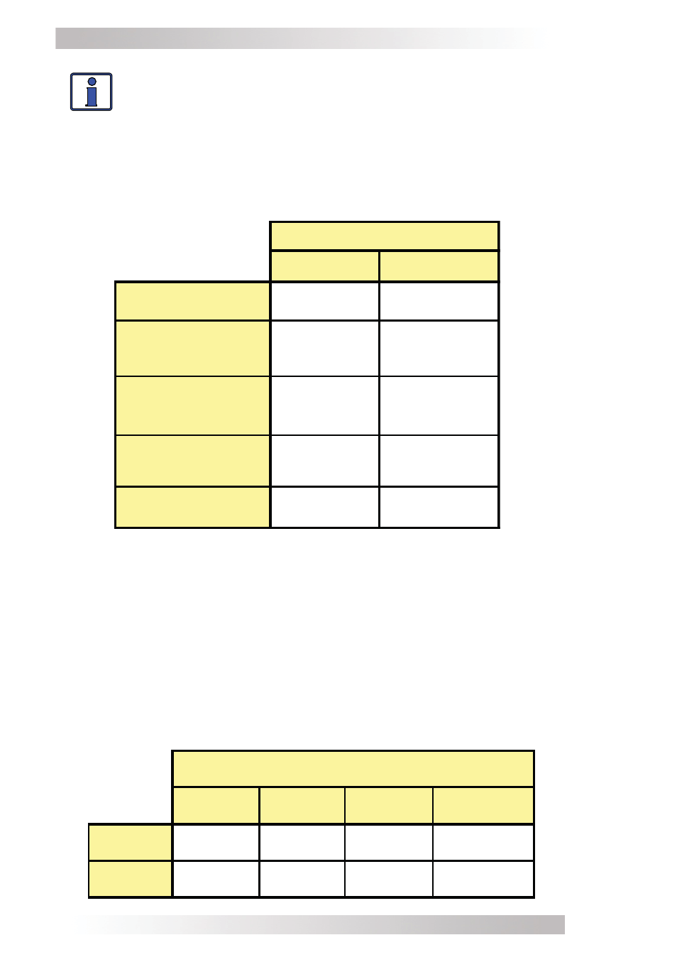
Table 1, Recommended DC Wire/Overcurrent Device
*Based on NEC, NFPA 70, Table 310-17, for 75° C single-insulated
cables in free air
Table 2, DC Wire Size For Increased Distance
MM612
MM1212
Full Load DC
Input Current
60 amps
125 amps
Maximum DC
Input Current
125 amps
175 amps
Minimum
Wire Size
# 4 AWG
# 1 AWG
Maximum DC
Overcurrent Device*
125 amps
200 amps
DC Ground
Wire Size
# 6 AWG
# 6 AWG
Inverter Model
If the inverter is expected to operate at a distance greater than three
feet from the battery bank, the DC wire will need to be increased to
overcome the increase in resistance – which affects the performance
of the inverter. Continue to use the overcurrent device and DC ground
wire previously determined from Table 1 and then, refer to Table 2 to
determine the minimum DC wire size you need for various distances
based on your inverter model.
3 ft or less
3 to 5 ft
5 to 10 ft
10 to 15 ft
MM612
#4 AWG
#2 AWG
#1/0 AWG
#2/0 AWG
MM1212
# 1 AWG
#1/0 AWG
#2/0 AWG
not
recommended
Minimum recommended DC wire size (one way)