Options - none; bypass with no options – Yaskawa E7L Drive Bypass User Manual
Page 99
Programming 5 - 7
Discussion of Table 5.2 Option-Dependent Bypass Parameter Settings:
Drive Parameter Settings for Various Combinations of Bypass and Options
Notes:
See Appendix D, Communications, for additional information on serial communication.
Hand mode run/stop for Drive and Bypass is always via the front control panel HAND selector key.
The HAND/OFF/AUTO selector keys must be in AUTO position if serial communication is to be used to control the
Drive.
For “monitoring only” of Drive parameters and operation, via serial communication, the user needs only to set-up the
H5-0X "Serial Com Setup" parameters. All other parameters may remain as they were factory programmed for the
Bypass unit and options.
Option L, LonWorks serial communication always requires DIP switch S1-1 (terminating resistor) to be ON. See the
LonWorks Option Installation Guide (IG.AFD.20.LONWORKS) for additional parameter setting instructions. Options
J, U or V require a terminating resistor only when the Drive is the last device on the serial communication chain.
To add a speed potentiometer at terminals TB3-1 to TB3-3 for HAND mode speed command: Configure terminal
TB3-3 to connect to Drive terminal A1 by placing DIP switch S1-3 in the Off position and DIP switch S1-4 in the On
position:
For an E7L with no options, as in line 2 of Table 5.2, change to have H3-09 = 2 and ensure that H3-13 = 1 (all
other parameters per line 2 of Table 5.2)
For an E7L with serial communications, as in lines 4, 5 and 6 of Table 5.2, change b1-01 = 1, H3-09 = 2, and
H3-13 = 0 (all other parameters per line 4, 5 or 6 of Table 5.2)
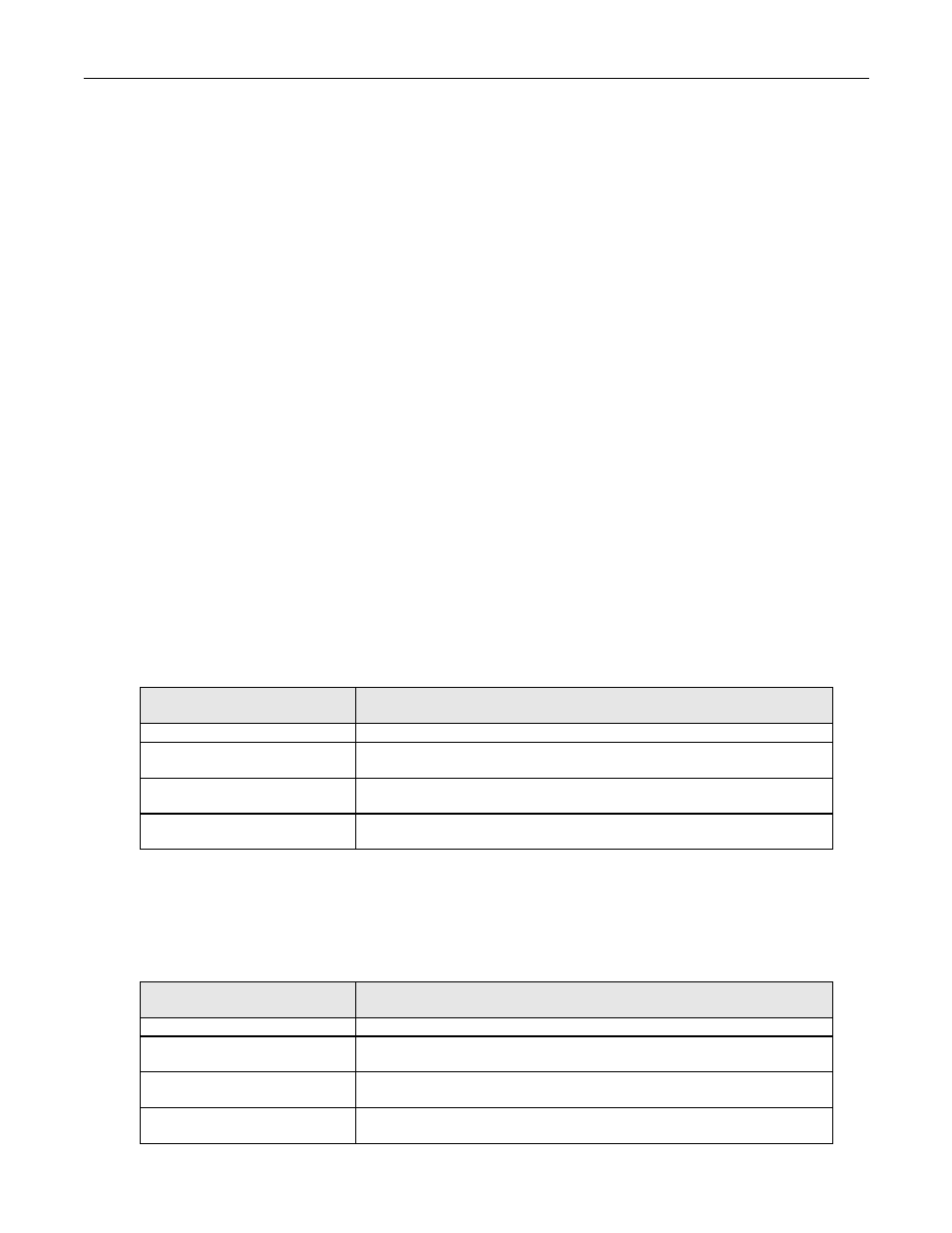
Options - None; Bypass with no options:
Hand mode speed command from Keypad/Operator.
Auto mode speed command input signal, 4-20 mA applied to Terminal TB3-3 (Drive terminal A2).
Auto mode run/stop contact closure for Drive and Bypass applied to terminals TB1-2 and TB1-9.
Options - None; Bypass with no options:
Hand mode speed command from Keypad/Operator.
Auto mode speed command input signal, 0-10 VDC applied to Terminal TB3-3 (Drive terminal A2).
Auto mode run/stop contact closure for Drive and Bypass applied to terminals TB1-2 and TB1-9.
Significant
Parameter Setting
Drive Operational Result
b1-01 = 1: Terminals (default)
Speed command source = Terminals
H3-08 = 2: 4-20 mA (default)
Drive Terminal A2 is programmed for 4-20 mA (Note – Control PCB DIP switch
S1-2 must also be ON)
H3-09 = 0: Frequency Bias
Drive Terminal A2 function is set to “bias” the terminal A1 input. Terminal A1 is
not used, therefore the A2 “bias” signal becomes the speed command.
H1-03 = 3: Multi-Step Ref 1
(default)
A Drive terminal S5 input contact closure selects d1-02 (keypad) as a preset speed.
This input contact is closed when H/O/A = Hand.
Significant
Parameter Setting
Drive Operational Result
b1-01 = 1: Terminals (default)
Speed command source = Terminals
H3-08 = 0: 0-10 VDC
Drive Terminal A2 is programmed for 0-10 VDC (Note – Control PCB DIP switch
S1-2 must also be OFF)
H3-09 = 0: Frequency Bias
Drive Terminal A2 function is set to “bias” the terminal A1 input. Terminal A1 is
not used, therefore the A2 “bias” signal becomes the speed command.
H1-03 = 3: Multi-Step Ref 1
(default)
A Drive terminal S5 input contact closure selects d1-02 (keypad) as a preset speed.
This input contact is closed when H/O/A = Hand.