Analog outputs, Configuring the analog outputs, Table 2.9 analog outputs – Yaskawa E7L Drive Bypass User Manual
Page 45: Programming the analog outputs, Table 2.10 analog output proportional variables, Electrical installation 2 - 13
Electrical Installation 2 - 13
Analog Outputs
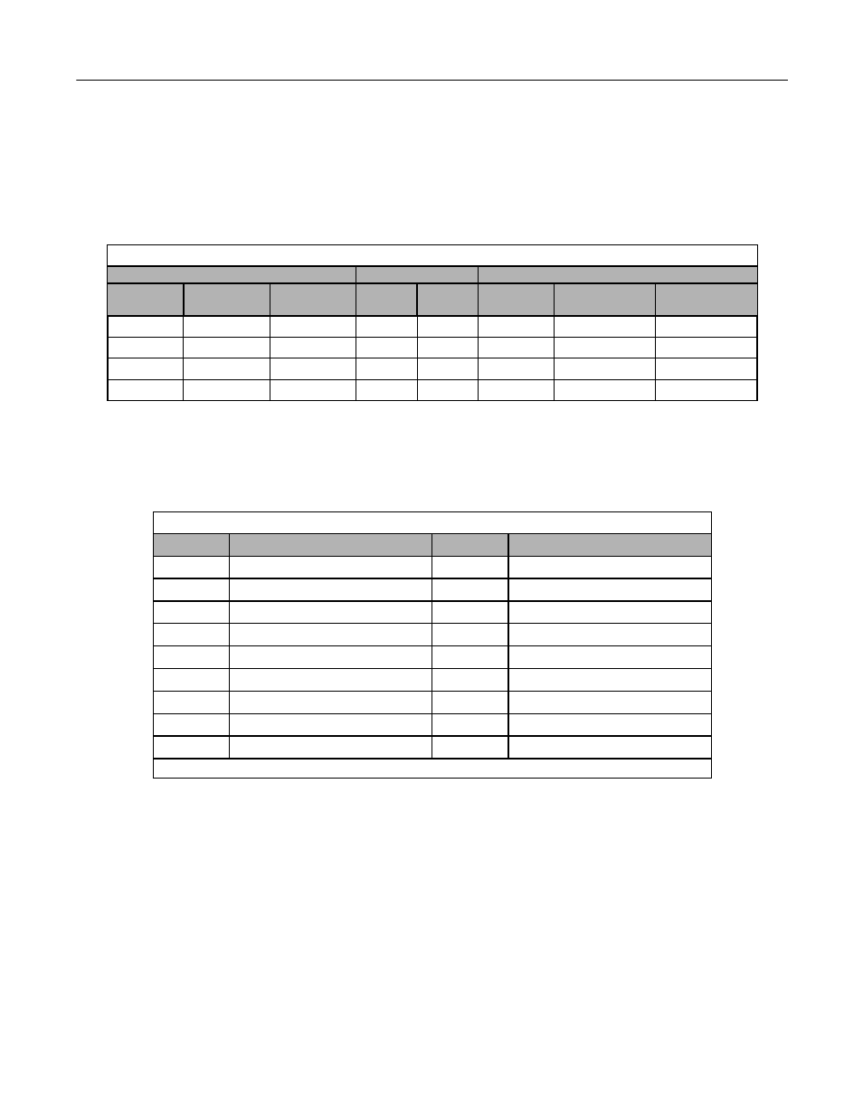
Two analog outputs are provided, both can be configured for a signal level of 0 to 10 VDC or 4 to 20 mA. The signal level is
controlled by the position of jumpers J2 and J3 (see Figures 1.8 and 1.9 for location) on Control PCB A2 and by the values
selected for Drive parameters H4-07 and H4-08.
Configuring the Analog Outputs:
Programming the Analog Outputs:
The TB3-4 and TB5-6 analog outputs can be programmed to be proportional to any of the following Drive variables.
See Page A-17 or the H4-0X parameters in the programming manual, TM.E7.02 for additional programming details.
Table 2.9 Analog Outputs
Terminals
Jumper Position
Drive
Analog
Output
AC
Common
Signal Level
J2
J3
Terminal *
Parameter
H4-07
Parameter
H4-08
TB3-4
TB3-1
4-20 mA
1-2
N/A
FM
2: 4-20 mA
N/A
TB3-4
TB3-1
0-10 VDC
2-3
N/A
FM
0: 0-10 V
N/A
TB5-6
TB5-7
4-20 mA
N/A
1-2
AM
N/A
2: 4-20 mA
TB5-6
TB5-7
0-10 VDC
N/A
2-3
AM
N/A
0: 0-10 V
* = For Drive programming reference
Table 2.10 Analog Output Proportional Variables
Setting
Description
Setting
Description
1
Frequency Ref
20
SFS Output*
2
Output Freq
24
PI Feedback
3
Output Current
31
Not Used
6
Output Voltage
36
PI Input
7
DC Bus Voltage
37
PI Output
8
Output kWatts
38
PI Setpoint
15
Term A1 Level
51
Auto Mode Fref
16
Term A2 Level
52
Hand Mode Fref
18
Mot SEC Current
53
PI Feedback 2
* SFS is the internal soft starter signal. This signal is generated from the reference and often it passes through the accel/ decel functions.