Terminating resistor, Fig 2.9 terminating resistor, Fig 2.10 rs-485 communication connection – Yaskawa E7L Drive Bypass User Manual
Page 47: Electrical installation 2 - 15
Electrical Installation 2 - 15
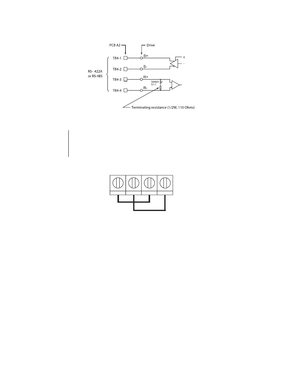
Terminating Resistor
The terminating resistance must be turned ON only if the Drive is at the very end of the Serial Communication chain. Set the
terminating resistance by turning ON DIP switch S1-1.
Fig 2.9 Terminating Resistor
Fig 2.10 RS-485 Communication Connection
IMPORTANT
1. Separate the communication cables from the main circuit cables and control circuit wiring.
2. Use shielded cables for the communication wiring, and use proper shield clamps.
3. When using RS-485 communication, connect TB4-1 to TB4-3, and TB4-2 to TB4-4, on the control circuit
terminal board. See Fig 2.10 below.
4. Connect shield at one end only.
TB4-3
TB4-4
TB4-1
TB4-2
TB4 on Control PCB A2
This manual is related to the following products: