Digital operator and control panel display – Yaskawa E7L Drive Bypass User Manual
Page 58
Control Panel 3 - 2
Digital Operator and Control Panel Display
The various items included on the Digital Operator Display and Control Panel are described below.
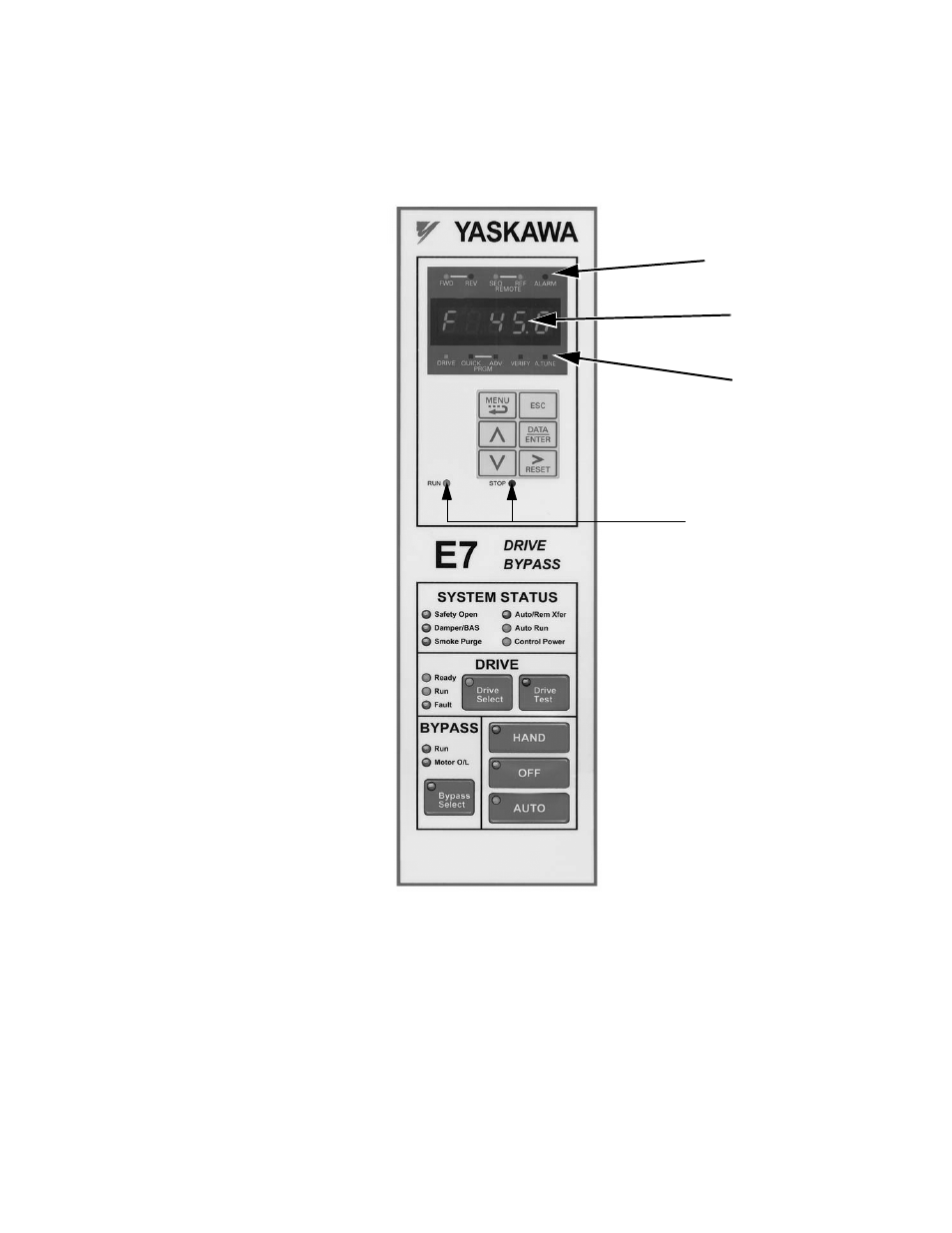
Fig 3.1 E7 Bypass Control Panel Component Names and Functions
The front control panel has a digital alpha/numeric display and keypad, in the upper portion, for Drive operation and program-
ming. The row of LEDs above the alpha/numeric display indicate Drive operational status. See Table 3.2 for an explanation.
The row of LEDs below the alpha/numeric display indicate the Drive menu that is presently active.
The lower portion of the front control panel displays the operating mode status via LEDs and controls the HAND/OFF/AUTO
functions for both the Drive and Bypass. The general rule for LED colors, in the lower portion of the control panel, is:
Green = Normal Status
Amber = Abnormal Status
Red =
Fault
Status
RUN & STOP Indicators
Drive Keypad Operator
Drive Digital
Operator/Keypad
Status Indicating LEDs
H/O/A Control Keypad
Drive/Bypass and
HAND/OFF/AUTO
Selector Keys
{
{
}
}
}
Drive Operational Status
Alpha-Numeric
Menu Indicating
LED Digital Display
LEDs