Analog input (drive speed control circuit) wiring, Fig 2.8 analog input terminal configuration – Yaskawa E7L Drive Bypass User Manual
Page 44
Electrical Installation 2 - 12
Analog Input (Drive Speed Control Circuit) Wiring
Keep this lead length as short as possible (50 m max.) to maintain signal quality. Insulated twisted shielded pair wire (2 con-
ductor # 18 ga, Belden 8760 or equivalent) is required. Do not run these wires in the same conduits as other AC power or con-
trol wires. The shield must be connected on this end only, stub and isolate the other end. The signal employed is 4 to 20 mA
with parameter H3-08 set for “2: 4 - 20 mA”. For 0 to 10 VDC, parameter H3-08 is set for “0: 0 - 10 VDC” and the control
PCB DIP switch S1-2 must be in the OFF position.
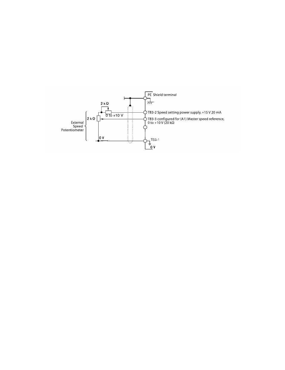
When setting speed commands from an external speed potentiometer (and not from a Digital Operator), use shielded twisted-
pair wires and ground the shield to terminal PE, as shown in Figure 2.8. Terminal numbers and wire sizes are shown in
Table 2.13.
Fig 2.8 Analog Input Terminal Configuration