Bypass operation description, Start up and operation 4 - 8 – Yaskawa P7B Drive Bypass User Manual
Page 90
Start Up and Operation 4 - 8
Bypass Operation Description
(For manual switch positions, control inputs and switch selectable functions.)
The Bypass has two modes of operation: Bypass and Drive. When in the Bypass mode the connected motor is run directly
from the incoming AC line, whereas in Drive mode the motor is run from the Drive output. The DRIVE/BYPASS switch
located on the front panel determines operating mode. Within each operating mode are two methods of control; HAND and
AUTO. The HAND/OFF/AUTO switch on the front panel determines this control method.
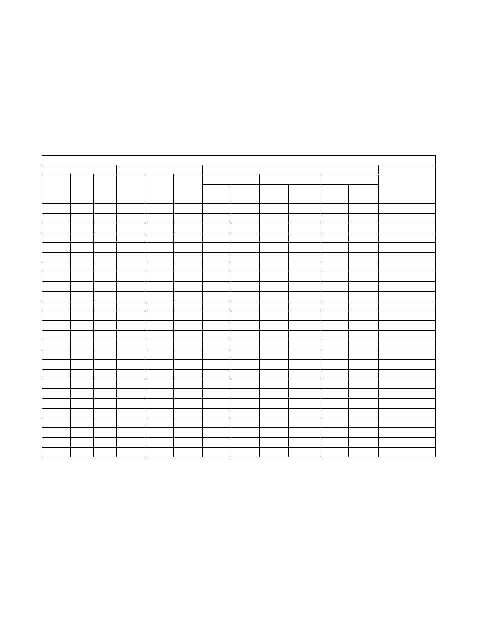
Table 4.1 provides a look at various combinations of the control panel selector switch positions, control inputs to TB1 and the
status of the switch selectable options.
Note: A blank cell indicates the input can be in any of the possible positions.
* = Drive energized, output contactor open.
Table 4.1 Definitions:
H/O/A = Hand/Off/Auto
TB = Terminal Block
D/B = Drive/Bypass
S10X = Slide Switch Number
N/T = Normal/Test
X = Closed Contacts or Enabled
DRV FLT = Drive Fault Contacts
0 = Open Contacts or Disabled
Table 4.1 Bypass Inputs and Operating Mode
Selector Switches
Contact Closure Inputs
Switch Selectable Functions
Operating Mode
Result
H/O/A
D/B
N/T
Run
TB1
3 & 4
Enable
TB1
5 & 6
Safety
TB1
1 & 2
Auto Xfer
Remote Xfer
Smoke Purge
S103
DRV
FLT
S104
TB1
25 & 26
S105
TB1
17 & 18
O
0
None
H
D
N
X
X
0
0
0
Drive
H
D
N
0
X
0
0
0
None
H
D
N
X
0
0
0
0
None
H
D
T
X
X
0
0
0
None
H
B
N
X
X
Bypass
H
B
T
X
X
Bypass*
H
B
N
0
X
0
None
H
B
N
X
0
0
None
A
D
N
X
X
X
0
0
0
Drive
A
D
N
X
0
X
0
0
0
None
A
D
N
X
X
0
0
0
0
None
A
D
T
X
X
X
0
0
0
None
A
B
N
X
X
X
Bypass
A
B
T
X
X
X
Bypass*
A
B
N
X
0
X
0
None
A
B
N
X
X
0
0
None
H
D
N
X
X
X
0
X
0
X
0
Drive
H
D
N
X
X
X
X
Bypass
H
D
N
X
X
X
X
Bypass
H
D
N
X
X
X
X
Bypass
O
D
N
X
X
X
X
Bypass
A
D
N
X
X
X
X
0
X
0
X
0
Drive
A
D
N
X
X
X
X
X
Bypass
A
D
N
X
X
X
X
X
Bypass
A
D
N
X
X
X
X
X
Bypass