Bypass unit enclosures, Physical installation 1 - 8, Drive nameplate information – Yaskawa P7B Drive Bypass User Manual
Page 20: Bypass unit model numbers
Physical Installation 1 - 8
"
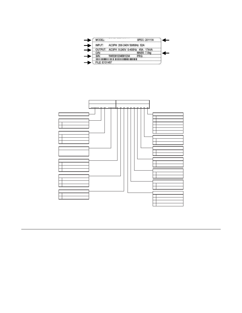
Drive Nameplate Information
A nameplate is also attached to the right side of the Drive inside the Bypass enclosure. The following nameplate is an example
for a standard Drive.
Fig 1.2 Drive Nameplate
(Example)
"
Bypass Unit Model Numbers
The model number on the nameplate of the Bypass unit indicates the enclosure, voltage, Drive rated current and options of the
Bypass unit in alphanumeric codes.
Fig 1.3 Bypass Unit Model Number
!
Bypass Unit Enclosures
All Bypass units are intended for non-hazardous locations. Various enclosure types are provided to protect against the applica-
tion environmental conditions:
Nema Type 1 Enclosures
are constructed for indoor use to provide a degree of protection against incidental contact with
enclosed electrical equipment and falling dust or dirt.
NEMA Type 12 FVFF Enclosures.
NEMA provides for both non-ventilated and ventilated NEMA 12 enclosures. When
ventilated, a suffix to the type number defines the ventilation method. A NEMA 12 FVFF enclosure has Forced Ventilation
with inlet air Filter and outlet air Filter. The internal pressure is positive with respect to the ambient pressure. UL does not
recognize NEMA 12 ventilated enclosures, therefore, these enclosures are designated NEMA 1 for UL purposes.
Input Power Specifications
Output Power Specifications
Drive Model Number
Drive Enclosure and
Revision Code
Weight
Serial Number
UL File Number
CIMR-P7U2011
V B
- - - R - - S - - L
-
G
V
H
B
-
D
M
A
B
-
P
-
-
S
D
A
-
-
W
N
E
-
-
K
F
-
X
Z
R
Profibus
3-15 PSI Transducer
NEC Rated Amps
Current
Voltage
208V
230/240V
480V
Speed Pot
P7 Bypass Configuraton
P 7 B
0 9 6
Enclosure
NEMA 1
NEMA 12
2 M
1 Motor (Standard)
None (Leave Blank)
None (Leave Blank)
None (Leave Blank)
None (Leave Blank)
None (Leave Blank)
None (Leave Blank)
None (Leave Blank)
None (Leave Blank)
Not Enabled (Leave Blank)
otor "OR"
2 Motor "AND"
Motor Control
(Ex.: "096" = 96A)
Load Reactor
4-20mA Output
4-20mA Output
Input Fuses
3% Bus Reactor
(1)
5% Bus Reactor
(1)
3% Input Reactor
(2)
Custom Nameplates
RFI Filter
BASE NUMBER
OPTIONS
Communications
DeviceNet
5% Load Reactor
Speed Pot
3-15 PSI Transducer
Fuses
Custom Nameplates
Input Filter
Cap Filter
Line Impedance
L LonWorks
Q Ethernet
V Modbus (Internal)
(1) 3% and 5% Bus Reactors are only available as an option on Drives up to
25HP at 208V and 30HP at 480V; larger Drives have a Bus Reactor as standard
(2) 3% Input Reactor, when combined with the standard Bus Reactor (available on
drives above 25HP at 208V and 30HP at 480V), yields a total of 5% input
impedance