Programming 5 - 26 – Yaskawa P7B Drive Bypass User Manual
Page 120
Programming 5 - 26
Options - S
"Speed Pot."; Bypass with PI Control and speed potentiometer for speed control and setpoint:
Hand mode speed command from speed potentiometer.
Auto mode PI Setpoint from speed potentiometer.
Auto mode PI Feedback input signal, 0-10 VDC applied to Drive terminal A2.
Auto mode run/stop contact closure for Drive and Bypass applied to terminals TB1-3 and TB1-4.
Options - S
"Speed Pot."; Bypass with PI Control and speed potentiometer for speed control:
Hand mode speed command from speed potentiometer.
Auto mode PI Setpoint from Keypad/Operator.
Auto mode PI Feedback input signal, 0-10 VDC applied to Drive terminal A2.
Auto mode run/stop contact closure for Drive and Bypass applied to terminals TB1-3 and TB1-4.
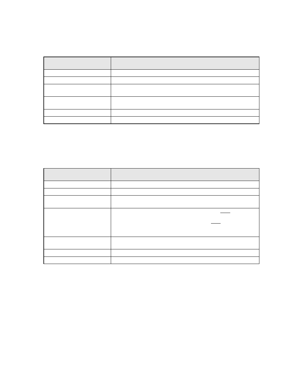
Significant
Parameter Setting
Result
b1-01 = 1: Terminals (default)
Speed command (Hand) and PI setpoint (Auto) source = Terminals
b5-01 = 1: Enable
Enable PI mode of operation
H1-03 = 19: PI Disable
A terminal S5 input contact closure disables PI mode. This input contact is closed
when H/O/A = Hand.
H3-08 = 0: 0-10 VDC
Terminal A2 is programmed for 0-10 VDC (Note – Control PCB DIP switch S1-2
must also be OFF)
H3-09 = B: PI Feedback
Terminal A2 function is set to provide PI feedback for closed loop control
H3-13 = 1: Main Fref TA2
Terminal A2 (the feedback terminal) serves as the main input
Significant
Parameter Setting
Result
b1-01 = 1: Terminals (default)
Speed command (Hand) and PI setpoint (Auto) source = Terminals
b5-01 = 1: Enable
Enable PI mode of operation
H1-03 = 19: PI Disable
A terminal S5 input contact closure disables PI mode. This input contact is closed
when H/O/A = Hand.
H1-04 = 6D: Auto Mode Sel
S6 must be jumpered to S5
A terminal S6 input contact opening (H/O/A = Auto) puts the Drive in “Hand”
mode to source the PI Setpoint from the Keypad/Operator (overrides b1-01). A ter-
minal S6 input contact closure (H/O/A = Hand) puts the Drive in “Auto” mode to
allow b1-01 to determine the speed command source. This input is jumpered to S5,
therefore the contact is closed when H/O/A = Hand.
H3-08 = 0: 0-10 VDC
Terminal A2 is programmed for 0-10 VDC (Note – Control PCB DIP switch S1-2
must also be OFF)
H3-09 = B: PI Feedback
Terminal A2 function is set to provide PI feedback for closed loop control
H3-13 = 1: Main Fref TA2
Terminal A2 (the feedback terminal) serves as the main input