Shunt connector cn15, Electrical installation 2 - 17 – Yaskawa P7B Drive Bypass User Manual
Page 55
Electrical Installation 2 - 17
!
Shunt Connector CN15
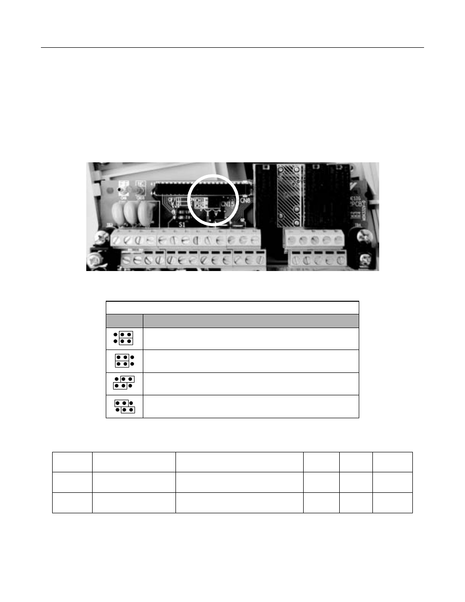
The shunt connector CN15 is described in this section. Shunt connector along with parameters H4-07 and H4-08 select the
signal range of the analog output terminals FM and AM.
Shunt connector CN15 is only available when the optional Terminal Card with the 4-20mA Analog Output Monitor is
installed. See Chapter 7 for installation of the optional Terminal Card.
The function of various shunt connector CN15 configurations is shown in Table 2.8.
Fig 2.12 Shunt Connector CN15 Location
The software configuration for the analog output monitor signal type is listed below:
Table 2.8 Shunt Connector CN15 Configuration Options
CN15
Analog Output Monitor Configurations
Voltage Output (0-10 VDC) for terminals FM-AC (CH1) and AM-AC (CH2)
Current Output (4-20mA) for terminals FM-AC (CH1) and AM-AC (CH2)
Voltage Output (0-10 VDC) for terminals FM-AC (CH1)
Current Output (4-20mA) for terminals AM-AC (CH2)
Current Output (4-20mA) for terminals FM-AC (CH1)
Voltage Output (0-10 VDC) for terminals AM-AC (CH2)
Parameter
No.
Parameter Name
Digital Operator Display
Description
Setting
Range
Factory
Setting
Menu
Location
H4-07
Terminal FM Signal Level
Selection
AO Level Select1
0: 0 - 10 V
2: 4-20 mA
0 or 2
0
Programming
H4-08
Terminal AM Signal Level
Selection
AO Level Select2
0: 0 - 10 V
2: 4-20 mA
0 or 2
0
Programming