B1 sequence – Yaskawa P7B Drive Bypass User Manual
Page 105

Programming 5 - 11
"
A1-04 Password Entry
Setting Range:
0 to 9999
Factory Default: 0
If parameters A1-01 through A1-03 and all of the A2 parameters are locked (unchangeable) they can be unlocked by entering the
correct password number into A1-04.
Once the correct password number is entered and the specified parameters are unlocked, a 2-Wire or 3-Wire initialization will reset
the password to 0000.
"
A1-05 Select Password
Setting Range:
0 to 9999
Factory Default: 0
When the value set into A1-04 does NOT match the value set into A1-05, parameters A1-01 thru A1-03 and A2-32 cannot be
changed. All other parameters determined by A1-01 can be changed. Parameter A1-05 can be accessed by displaying parameter
A1-04, then press and hold the RESET key along with the MENU key simultaneously.
!
b1 Sequence
The Sequence Group contains parameters associated with starting and stopping the Drive. Parameters involving the Run
Command, Speed Reference location, Stopping Method and Hand/Auto changeover are located in this group.
"
b1-01 Reference (Speed Command) Source Selection
This is one of the special parameter settings required by the Bypass logic circuit. See Table 5.1.
The addition of serial communication to the Drive and Bypass unit, after shipment to the job site, would be the only reason for
changing this parameter. See Table 5.2 for the parameter settings required to enable serial communication in the field.
In order to run the Drive and motor with the BYPASS/DRIVE switch in the DRIVE position: the Drive must receive a Run com-
mand and a speed command. Parameter b1-01 specifies from where the speed command is received when the Drive is in the
AUTO mode. Switching into the AUTO mode can be done by turning the Hand/Off/Auto selector switch to AUTO while the
Drive is stopped.
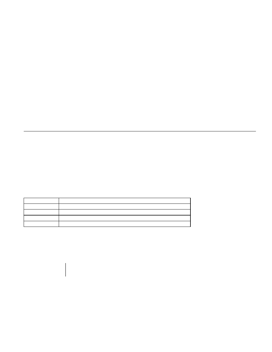
Setting
Description
0
Operator - Digital Preset Speed d1-01
1
Terminals - Analog Input Terminal A1 (or Terminal A2, see Parameter H3-13)
2
Serial Com - RS-485 Terminals R+, R-, S+ and S-
3
Option PCB - Option Board connected at 2CN
IMPORTANT
If a Run command is input to the Drive but no corresponding speed command is input, the Run indicator on
the digital operator will turn on and the STOP indicator on the digital operator will blink.
