3 overview, 1 appearance and connectors, 2 status indicators (leds) – Yaskawa JAPMC-CM2304-E User Manual
Page 26
2.3 Overview
2.3.1 Appearance and Connectors
2-10
2.3 Overview
2.3.1 Appearance and Connectors
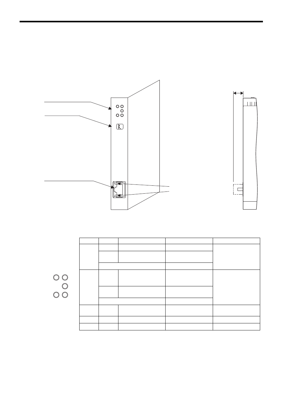
The following illustration shows the appearance of the 263IF-01 Module and provides the external dimensions of the
connector.
2.3.2 Status Indicators (LEDs)
The following table shows the status of the 263IF-01 Module indicated by the LED indicators.
For details on the Module status indicated by the LED indicators, refer to 6.1 Status Indication by LED Indicators on
page 6-2.
EtherNet/IP connector
100Base-TX/10Base-T
Status indicators
(LEDs)
Switches
263IF-01
NS
IP
RX
MS
TX
TEST
INIT
ON
OFF
LINK
100M
EtherNet/IP
Communication status
indicator (LED)
(contained in the connector)
(25 mm)
NO
Indicator
Color
Meaning When Lit
Meaning When Flashing
Meaning When Not Lit
MS
Green
Operating normally
Device not set
Module power supply
disconnected/Startup
failure
Red
Module error
(Unrecoverable)
Module error
(Recoverable)
Alternately flashing green/red
During self-testing
NS
Green
Operating normally
Connection being estab-
lished, or no I/O alloca-
tions
Communication power
supply disconnected/No
IP address
Red
Error
(Duplicated IP address)
Communication error
(Timeout)
Alternately flashing green/red
During self-testing
IP
Green
IP address acquisition
completed
–
IP address acquisition not
completed
TX
Green
Sending data
–
Not sending data
RX
Green
Receiving data
–
Not receiving data
NS
IP
RX
MS
TX