2 checking the inverter cabling, 3 mounting the protective covers – SMA SC 500CP-US User Manual
Page 93
SMA America, LLC
16 Commissioning
Installation Manual
SCCP-US-IA-US_en-41
93
16.2 Checking the Inverter Cabling
1. Ensure that all connections are executed in accordance with the circuit diagram.
2. Check that the AC, DC, and protective conductor cables are securely connected.
3. Ensure that there is equipotential bonding between the inverter and the mounting location.
4. Ensure that all connections in the interface cabinet are securely in place.
5. Attach all cables in the connection area to the cable support rail using cable ties.
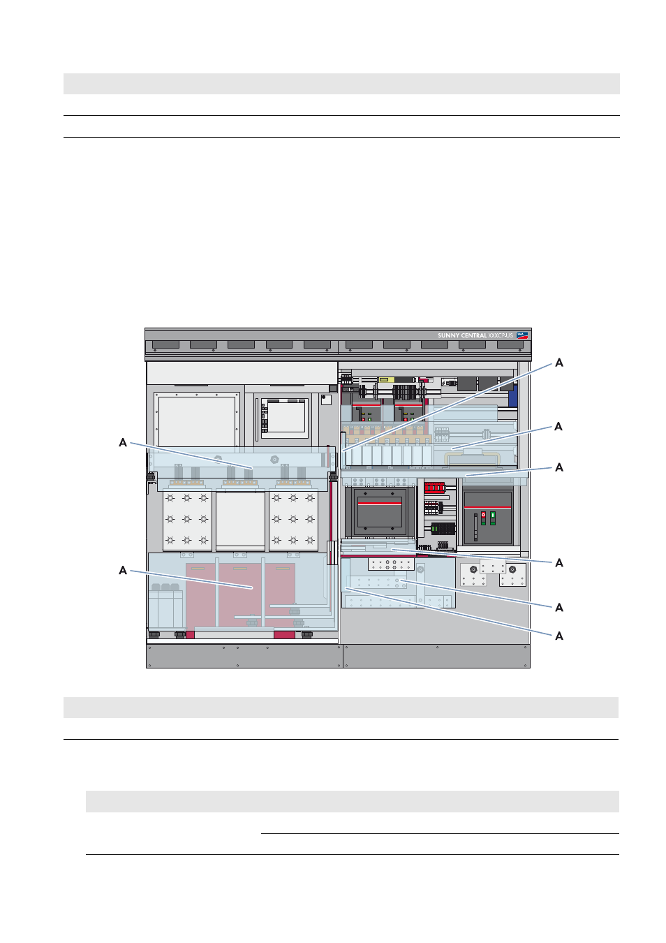
16.3 Mounting the Protective Covers
Before you switch on the inverter, all protective covers and panels must be mounted. ]
Figure 46: Position of the protective covers in the inverter
Procedure:
• Screw all protective covers into place. Tighten to the torque specified:
12.
Mount the panels.
13.
Switch on the inverter.
Position
Description
A
Protective cover
Protective covers
Torque
In the interface cabinet
In the connection area
7.4 ft.-lbs (10 Nm)
All others
2.2 ft.-lbs. (3 Nm)
Procedure
See