1 connection area, 1 inverter without integrated dc switch – SMA SC 500CP-US User Manual
Page 76
12 Cable Connection of External Devices in the Interface Cabinet
SMA America, LLC
76
SCCP-US-IA-US_en-41
Installation Manual
12 Cable Connection of External Devices in the Interface Cabinet
12.1 Connection Area
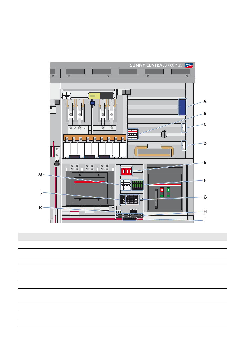
12.1.1 Inverter Without Integrated DC Switch
Figure 44: Terminals in the interface cabinet
Position
Description
A
Splice box*
B
Circuit breaker of the internal voltage supply*
C
Circuit breaker of the 24 V circuits
D
Circuit breaker of the grid monitoring
E
Overvoltage and lightning protection*
F
RJ45 network port network terminal
G
Terminals for external setpoint for reactive power and active power, external insulation monitoring,
transformer protection, remote shutdown
H
Cable support rail
I
Sealing plate
K
External voltage supply terminal
This manual is related to the following products: