1 dc connection with negative grounding – SMA SC 500CP-US User Manual
Page 61
SMA America, LLC
10 DC Connection
Installation Manual
SCCP-US-IA-US_en-41
61
☐ Use only copper terminal lugs or tin-plated aluminum lugs.
☐ Connect a maximum of two cables to the connection lug.
☐ Only use screws, nuts and washers included in the scope of delivery.
☐ The specified torques must always be complied with.
10.3 Overview of the DC Connection for the Option DC Fuse
With this connection option, you can use terminal lugs to connect the DC cables. An overview of drawings on the various
connection areas is provided below for orientation. Depending on the order option and how the modules are grounded,
the connection areas may look different.
The maximum number of DC inputs is: 9 x DC+, 9 x DC‒. A maximum of two cables may be connected per DC input.
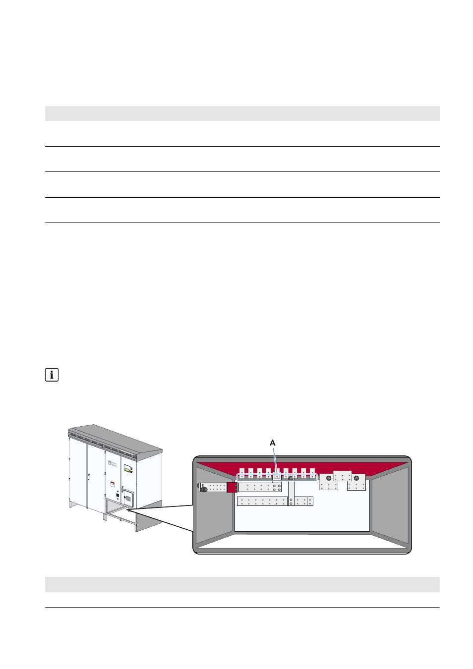
10.3.1 DC Connection with Negative Grounding
The DC cables previously fitted with terminal lugs are connected directly to the copper bus bars. You can connect a
maximum of two terminal lugs per DC input.
DC+ Connection with Terminal Lugs
Figure 29: Illustration of the positive terminal with the DC fuse option for connecting terminal lugs
Connection option
Cable cross-section
Torque
Copper terminal lug on copper bus bar
4 AWG to 800 kcmil
(25 mm
2
to 405 mm
2
)
44.5 ft.-lbs. (60 Nm)
Tin-plated aluminum terminal lug on copper
bus bar
4 AWG to 800 kcmil
(25 mm
2
to 405 mm
2
)
27.5 ft.-lbs. (37 Nm)
Tin-plated aluminum terminal lug on
tin-plated aluminum bus bar
4 AWG to 800 kcmil
(25 mm
2
to 405 mm
2
)
27.5 ft.-lbs. (37 Nm)
Copper terminal lug on tin-plated aluminum
bus bar
4 AWG to 800 kcmil
(25 mm
2
to 405 mm
2
)
27.5 ft.-lbs. (37 Nm)
Observe polarity
The polarity of the connection area depends on how the PV modules are grounded.
The following overview displays the positive terminal when the module has a negative grounding.
Position
Description
A
DC+ terminal (negative grounding)