1 dc connection with negative grounding – SMA SC 500CP-US User Manual
Page 65
SMA America, LLC
10 DC Connection
Installation Manual
SCCP-US-IA-US_en-41
65
10.4 Overview of the DC Connection for the Optional DC Busbar
With this connection option, the DC fuses are located in a DC main distribution or DC sub-distribution. There are no
DC fuses in the inverter. The cables are connected directly to the DC busbars.
The maximum number of DC inputs is: 10 x DC+, 4 x DC‒, or 4 x DC+, 10 x DC‒. A maximum of two cables may be
connected per DC input.
10.4.1 DC Connection with Negative Grounding
The DC cables previously fitted with terminal lugs are connected directly to the copper bus bars. You can connect a
maximum of two terminal lugs per DC input.
DC+ Connection with Terminal Lugs
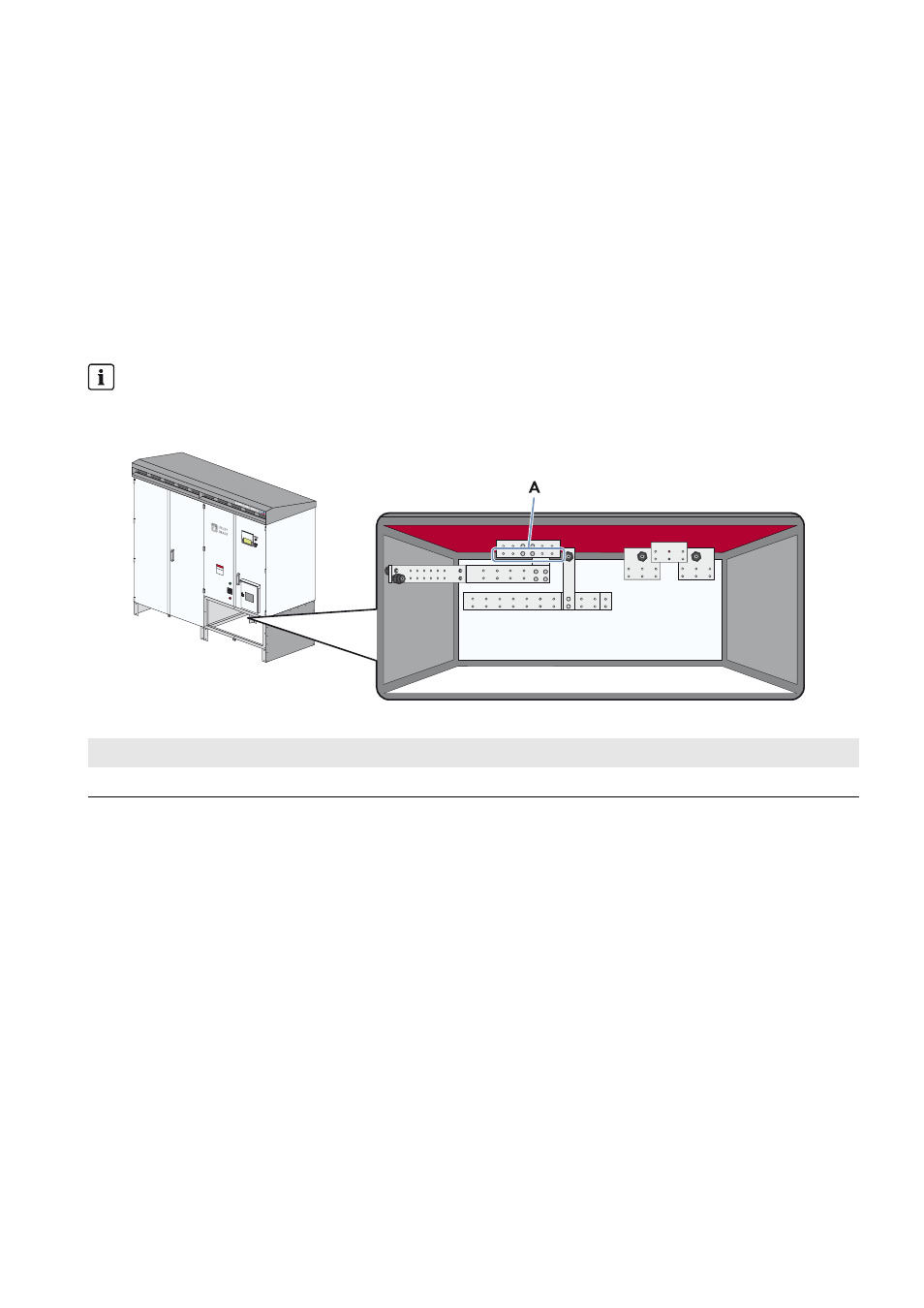
Figure 35: Illustration of the positive terminal with the DC busbar option for connecting terminal lugs
Observe polarity
The polarity of the connection area depends on how the PV modules are grounded.
The following overview displays the positive terminal when the module has a negative grounding.
Position
Description
A
DC+ terminal (negative grounding)