SMA STP 12000TL-US User Manual
Page 67
1. Mount the replacement device (see Section 5, page 19) and make the electrical connections
2. If needed, install interfaces in the replacement device and connect the interfaces (see the
interface manual).
3. If there is a label with "transport lid" affixed to the upper lid of the replacement device, replace
the upper enclosure lid of the replacement device with the upper enclosure lid of the defective
inverter.
Danger to life due to high voltages
Wait 20 minutes before removing the upper enclosure lid to allow residual voltages to discharge.
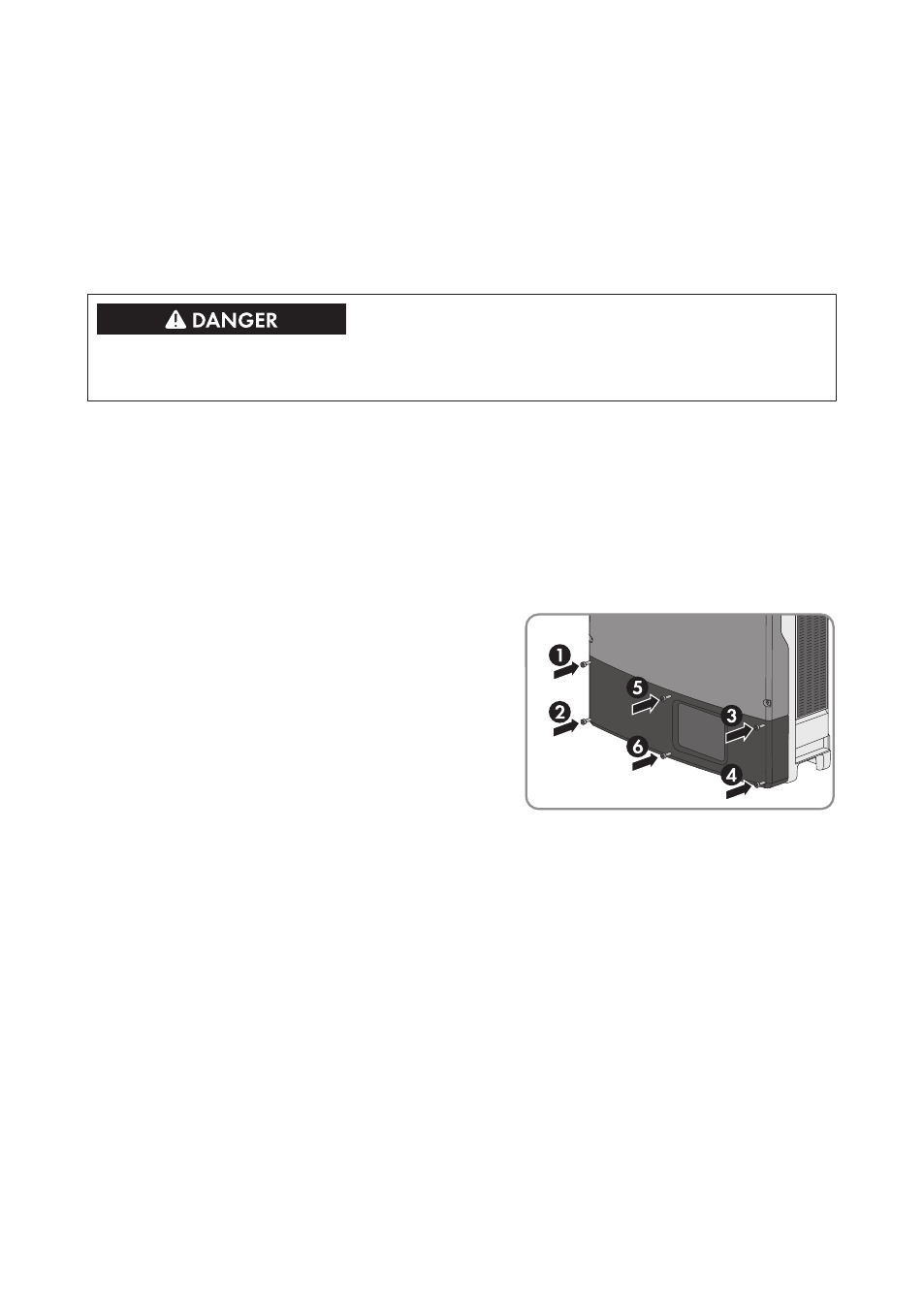
• Loosen the screws of the upper enclosure lid using an Allen key (AF 4) and remove the
enclosure lid.
• Position the upper enclosure lid with the six screws and conical spring washers on the
enclosure and tighten it using an Allen key (AF 4) in the order 1 to 6 (torque: 6 Nm ±
0.3 Nm).
4. Insert the lower enclosure lid from above and flip it down. Use the enclosure lid of the
defective inverter for this if there is a label with "transport lid" affixed to the enclosure lid of the
replacement device. The screws must protrude from the lower enclosure lid.
5. Tighten all six screws in the lower enclosure lid
with an Allen key (AF 3) in the order 1 to 6
(torque: 2 Nm ± 0.3 Nm). By tightening the
screws in the prescribed order, you avoid
warping the lid, which would keep it from
sealing correctly.
Useful hint: If the screws fall out of the lower
enclosure lid, insert the long screw into the lower
middle hole and the five short screws into the
other holes.
6. Commission the replacement device (see Section 7, page 37). Remount the DC load-break
switch of the defective inverter to the replacement device.
7. Configure the replacement device (see Section 8, page 38).
8. Replace the replacement device in the communication product.
Shipping the Defective Inverter
1. If necessary, position the upper enclosure lid with the six screws and conical spring washers
on the enclosure and tighten it using an Allen key (AF 4) in the order 1 to 6 (torque: 6 Nm ±
0.3 Nm).
2. Insert the lower enclosure lid from above and flip it down. The screws must protrude from the
lower enclosure lid.
13 Procedure for Receiving a Replacement Device
SMA Solar Technology AG
Installation Manual
67
STP12-24TL-US-IA-en-16