5 connecting the inverter to the network, Connecting the inverter to the network – SMA STP 12000TL-US User Manual
Page 35
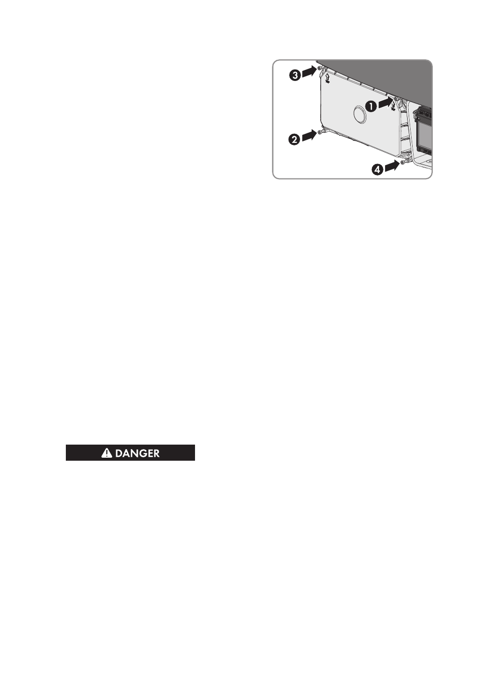
15. If no additional grounding is to be connected,
reattach the DC protective cover. Tighten all four
screws with an Allen key (AF 3) in the order 1 to
4 (torque: 3.5 Nm (31 in-lb)).
6.5
Connecting the Inverter to the Network
Cable requirements:
The cable length and quality affect the quality of the signal. Observe the following cable
requirements.
☐ Cable type: 100BaseTx
SMA recommends cable type "SMA COMCAB-OUTxxx" for outdoor use and cable type
"SMA COMCAB-INxxx" for indoor use, available in lengths xxx = 100 m (328 ft), 200 m
(656 ft), 500 m (1,640 ft), 1,000 m (3,281 ft)
☐ Cable category: Cat5, Cat5e, Cat6, Cat6a or Cat7
☐ Plug type: RJ45 of Cat5, Cat5e, Cat6 or Cat6a
☐ Shielding: SF/UTP, S/UTP, SF/FTP or S/FTP
☐ Number of insulated conductor pairs and insulated conductor cross-section: at least
2 x 2 x 0.22 mm² (2 x 2 x 24 AWG)
☐ Maximum cable length between two nodes when using patch cables: 50 m (164 ft)
☐ Maximum cable length between two nodes when using installation cables: 100 m (328 ft)
☐ UV-resistant for outdoor use
Procedure:
1.
Danger to life due to electric shock
• Disconnect the inverter from all voltage sources (see Section 9, page 41).
2. Connect one end of the network cable to the inverter:
• Remove the filler plugs from the network connection opening on the inverter.
• Attach the conduit to the opening.
• Lead the network cable through the conduit into the interior of the inverter.
• Release the screw of the display far enough to allow the display to be flipped up.
• Flip the display up until it snaps into place.
• Insert the network cable into one of the network jacks of the Webconnect Data Module.
• Flip the display down and fasten the display screw hand-tight.
6 Electrical Connection
SMA Solar Technology AG
Installation Manual
35
STP12-24TL-US-IA-en-16