6 format of g1_xist1 and g1_xist2, Figure 26 absolute value in g1_xist1, Figure 27 absolute value in g1_xist2 – HEIDENHAIN PROFINET User Manual
Page 42: Format of g1_xist1 and g1_xist2, Figure 26, Absolute value in g1_xist1, Figure 27, Absolute value in g1_xist2
PROFINET IO data description
42
4.6
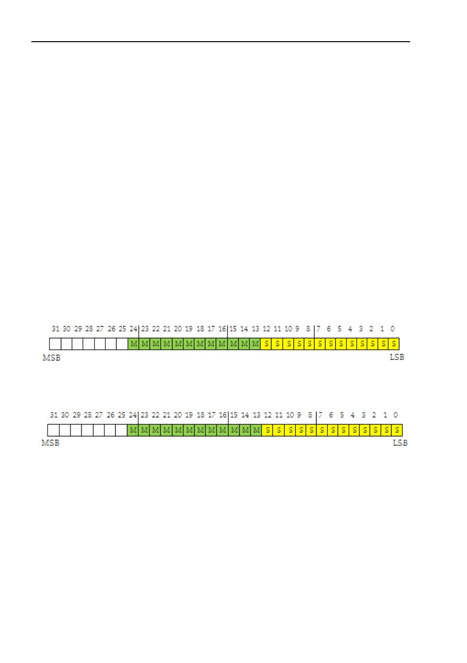
Format of G1_XIST1 and G1_XIST2
The G1_XIST1 and G1_XIST2 signals consist of the absolute posi-
tion value in binary format. By default the G1_XIST1 signal is equal
to the G1_XIST2 signal. The format of the actual position values in
G1_XIST1 and G1_XIST2 is shown below.
Format definition for G1_XIST1 and G1_XIST2:
All values are presented in binary format
The shift factor is always zero (right aligned value) for both
The setting in the encoder parameter data affects the position
value in both G1_XIST1 and G1_XIST2.
G1_XIST2 displays the error telegram instead of the position
Example:
25 bit multi turn absolute encoder (8192 steps per
revolution, 4096 distinguishable revolutions)
M = Multi turn value (Distinguishable revolutions)
S = Single turn value (number of steps per revolutions)
Figure 26
Figure 27