Figure 11, Terminal connections of bus line cables – HEIDENHAIN PROFIBUS-DP (DPV0) User Manual
Page 24
Absolute encoder installation
24
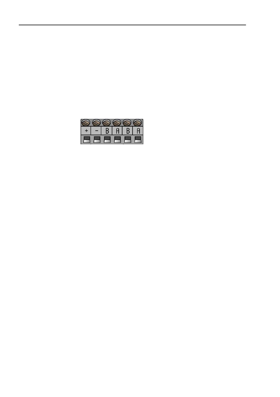
The cable gland encoders shall be equipped with twisted pair
shielded cable in accordance with EN 50170 and PROFIBUS
guidelines. The guidelines recommend a conductor area higher
than 0,34 mm
2
. Permissible outer cable diameter is ø 8 mm to
ø 10 mm for the bus line cables. Located inside the back cover are
four screw terminals containing the required bus line terminals
marked (A) and (B).
Cable glands not used should be replaced
with a M16 filler plug to ensure proper sealing.
The (A) terminal shall be used to connect the A-line.
The (B) terminal shall be used to connect the B-line.
Figure 11
Terminal connections of bus line cables
Note:
Tighten all screws in the terminal, even if no cable
has been attached.
Note:
The two A terminals are internally connected to
each other and the two B terminals are also
connected to each other so it does not matter to
which terminal the bus lines are connected to.
- TNC 122 User Manual (63 pages)
- TNC 122 Technical Manual (70 pages)
- TNC 360 Service Manual (157 pages)
- TNC 416 Technical Manual (510 pages)
- TNC 335 Technical Manual (581 pages)
- TNC 360 User Manual (237 pages)
- TNC 360 ISO-Programmierung (2 pages)
- TNC 415 (280 540) User Manual (227 pages)
- TNC 370D (92 pages)
- TNC 416 (289 pages)
- TNC 415 (280 540) Technical Manual (752 pages)
- TNC 415 (259 96x) Service Manual (195 pages)
- TNC 407 (280 580) User Manual (376 pages)
- iTNC 530 (340 420) Pilot (104 pages)
- TNC 407 (280 580) ISO Programming (333 pages)
- TNC 415 (280 540) Service Manual (252 pages)
- PT 880 Installation (112 pages)
- ND 100 User Manual (116 pages)
- ND 287 User Manual (147 pages)
- ND 280 Quick Start (12 pages)
- ND 200 (156 pages)
- ND 282 (10 pages)
- ND 287 Quick Start (26 pages)
- ND 282 B (39 pages)
- ND 281 A (44 pages)
- ND 281 B v.1 (53 pages)
- ND 281 B v.2 (65 pages)
- ND 221 v.2 (10 pages)
- ND 231 B v.2 (56 pages)
- ND 231 B v.1 (44 pages)
- ND 221 B v.2 (45 pages)
- ND 550 v.2 (8 pages)
- NDP 560 (10 pages)
- ND 523 (93 pages)
- ND 570 (8 pages)
- ND 750 v.2 (46 pages)
- ND 760 v.3 (72 pages)
- ND 770 v.1 (40 pages)
- ND 770 v.3 (41 pages)
- ND 760 E (44 pages)
- IOB 49 (21 pages)
- NDP 960 (68 pages)
- ND 780 Installation (132 pages)
- ND 970 (47 pages)
- ND 1100 Quick Start (36 pages)