Node address, Figure 2, Pcb-view of a cable gland profibus gateway – HEIDENHAIN PROFIBUS-DP (DPV0) User Manual
Page 10
Encoder gateway installation
10
2.1.1
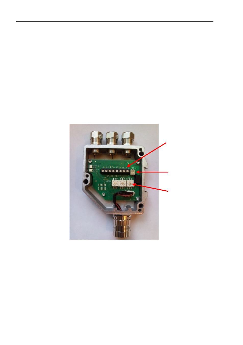
Node address
The node address of the encoder gateway can be set via three
decimal rotary switches located inside the back cover. The
weighting, x100, x10 and x1 are specified on the circuit board
besides the switches. Permissible address range is between 0
and 126 but the lower addresses 0 to 2 are usually used by the
master and not recommended to be used by the device. Each
address used in a PROFIBUS network must be unique and may
not be used by other devices.
The device address is only read and adopted when the gateway
power supply is switched on. A restart of the gateway is therefore
required in order to adopt changes done to the address settings.
Figure 2
PCB-view of a cable gland PROFIBUS gateway
Example
: To set the node address to 115, the switch to the left
(x100) shall be set to 1, the switch in the middle(x10)
should also be set to 1 and the switch to the right(x1)
shall be set to 5.
Screw terminals
Bus termination
switch (on/off)
Node address
switches ()