Reference system on milling machines, 1 f undamentals – HEIDENHAIN iTNC 530 (60642x-03) ISO programming User Manual
Page 95
HEIDENHAIN iTNC 530
95
3.1 F
undamentals
Reference system on milling machines
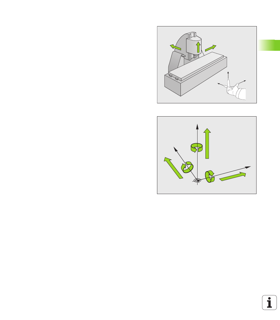
When using a milling machine, you orient tool movements to the
Cartesian coordinate system. The illustration at right shows how the
Cartesian coordinate system describes the machine axes. The figure
illustrates the right-hand rule for remembering the three axis
directions: the middle finger points in the positive direction of the tool
axis from the workpiece toward the tool (the Z axis), the thumb points
in the positive X direction, and the index finger in the positive Y
direction.
The iTNC 530 can control up to 18 axes. The axes U, V and W are
secondary linear axes parallel to the main axes X, Y and Z, respectively.
Rotary axes are designated as A, B and C. The illustration at lower right
shows the assignment of secondary axes and rotary axes to the main
axes.
In addition, the machine tool builder can define any number of auxiliary
axes identified by lowercase letters
+X
+Y
+Z
+X
+Z
+Y
W+
C+
B+
V+
A+
U+
Y
X
Z