HEIDENHAIN iTNC 530 (340 422) User Manual
Page 346
346
8 Programming: Cycles
8.4 Cy
cles f
o
r Milling P
o
c
k
ets, St
uds and Slots
8
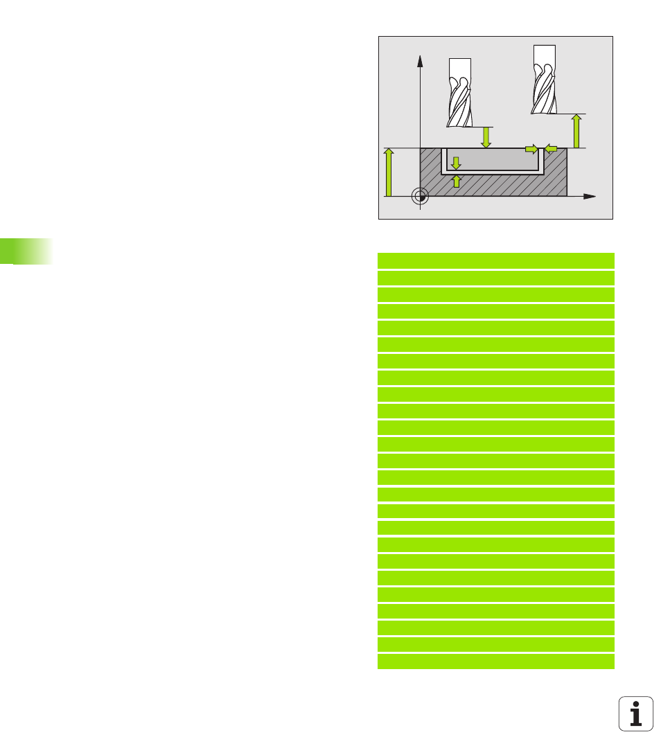
Set-up clearance
Q200 (incremental value): Distance
between tool tip and workpiece surface.
8
Workpiece surface coordinate
Q203 (absolute
value): Absolute coordinate of the workpiece surface
8
2nd set-up clearance
Q204 (incremental value):
Coordinate in the tool axis at which no collision
between tool and workpiece (clamping devices) can
occur.
8
Plunging strategy
Q366: Type of plunging strategy.
0 = vertical plunging. In the tool table, the plunging
angle ANGLE for the active tool must be defined as
90°. Otherwise the TNC displays an error message.
1 = helical plunging. In the tool table, the plunging
angle ANGLE for the active tool must be defined not
equal to 0. The TNC will otherwise display an error
message. Plunge on a helical path only if there is
enough space.
2 = reciprocating plunge. In the tool table, the
plunging angle ANGLE for the active tool must be
defined as not equal to 0. Otherwise the TNC
displays an error message.
8
Feed rate for finishing
Q385: Traversing speed of
the tool during side and floor finishing in mm/min.
Example: NC blocks
8 CYCL DEF 254 CIRCULAR SLOT
Q215=0
;MACHINING OPERATION
Q219=12
;SLOT WIDTH
Q368=0.2
;ALLOWANCE FOR SIDE
Q375=80
;PITCH CIRCLE DIA.
Q367=0
;REF. SLOT POSITION
Q216=+50
;CENTER IN 1ST AXIS
Q217=+50
;CENTER IN 2ND AXIS
Q376=+45
;STARTING ANGLE
Q248=90
;ANGULAR LENGTH
Q378=0
;STEPPING ANGLE
Q377=1
;NR OF REPETITIONS
Q207=500
;FEED RATE FOR MILLING
Q351=+1
;CLIMB OR UP-CUT
Q201=-20
;DEPTH
Q202=5
;PLUNGING DEPTH
Q369=0.1
;ALLOWANCE FOR FLOOR
Q206=150
;FEED RATE FOR PLNGNG
Q338=5
;INFEED FOR FINISHING
Q200=2
;SET-UP CLEARANCE
Q203=+0
;SURFACE COORDINATE
Q204=50
;2ND SET-UP CLEARANCE
Q366=1
;PLUNGING
Q385=500
;FEED RATE FOR FINISHING
9 CYCL CALL POS X+50 Y+50 Z+0 FMAX M3
X
Z
Q200
Q204
Q203
Q369
Q368