HEIDENHAIN TNC 426 (280 476) Pilot User Manual
Page 91
92
Digitizing
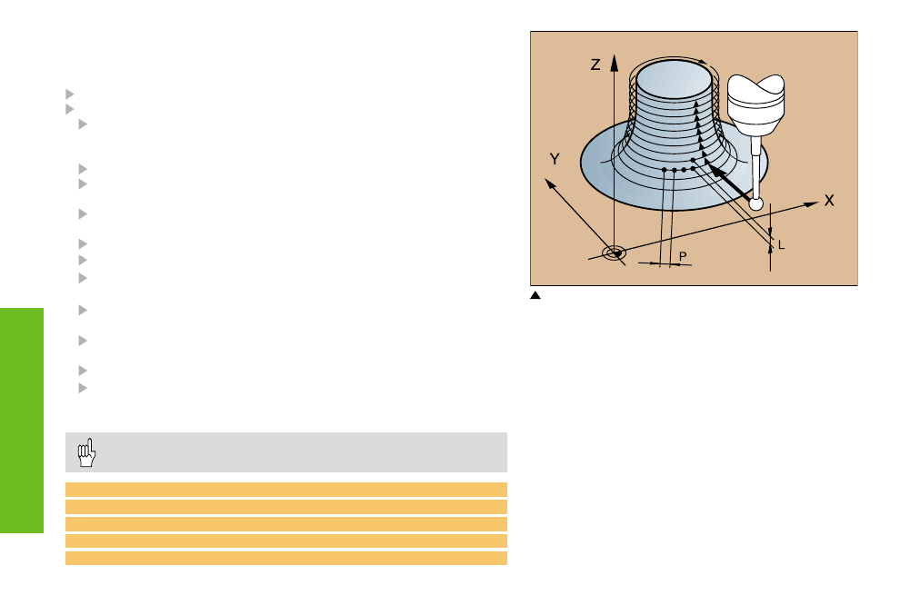
P: PP.INT = Probe point interval
L: L.SPAC = Line spacing
Digitizing Cycle CONTOUR LINES (17)
Cycle 17 CONTOUR LINES enables you to digitize a 3D surface
level by level.
Define Cycle 5 RANGE or 15 RANGE
TOUCH PROBE: Select Cycle 17 CONTOUR LINES
Time limit: If the touch probe has not orbited the model and
returned to the first touch point within this time, the TNC will
terminate the cycle. If you do not want a time limit, enter 0.
Starting point: Coordinates of the starting position
Axis and direction of approach: Coordinate axis and direction in
which the probe approaches the model
Starting probe axis and direction: Coordinate axis and direction in
which the probe begins scanning the model
Feed rate F: Maximum digitizing feed rate
Min. feed rate: Feed rate for scanning the first line
Feed rate reduction at edges: Distance at which the TNC begins to
reduce the scanning feed rate before steep edges
Min. line spacing: Minimum height moved to start the next
line at slightly inclined surfaces
Line spacing and direction: Maximum height moved to start the
next contour line
Max. probe point interval
Tolerance value: The TNC suppresses the storage of probe points
whose distance from a straight line defined by the last two stored
points is less than the tolerance value.
The line spacing and max. probe point interval cannot exceed
20 mm!
10 TCH PROBE 17.0 CONTOUR LINES
11 TCH PROBE 17.1 TIME: 200 X+50 Y+0
12 TCH PROBE 17.2 ORDER Y+/X+
13 TCH PROBE 17.3 F1000 FMIN 400 MIN.L.SPAC:0.2
L.SPAC:0.5 PP.INT:0.5 TOL:0.1 DIST 0.5