Rosemount 3300 series, Reference manual – Emerson Guided Wave Radar Level and Interface Transmitters 3300 User Manual
Page 118
Reference Manual
00809-0100-4811, Rev CA
February 2006
Rosemount 3300 Series
A-14
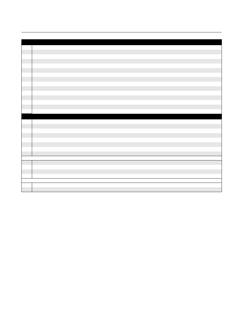
Code Hazardous Locations Certifications
NA
No Hazardous Locations Certifications
E1
ATEX Flameproof
E5
FM Explosion Proof
E6
CSA Explosion Proof
E7
IECEx Flameproof
I1
ATEX Intrinsic Safety
I5
FM Intrinsic Safety and Non-Incendive
I6
CSA Intrinsic Safety and Non-Incendive
I7
IECEx Intrinsic Safety
KA
ATEX and CSA Flameproof/Explosionproof
KB
FM and CSA Explosionproof
KC
ATEX and FM Flameproof/Explosionproof
KD
ATEX and CSA Intrinsic Safety
KE
FM and CSA Intrinsic Safety
KF
ATEX and FM Intrinsic Safety
Code Options
M1
Integral digital display
BT
Bar Code Tag with tag number and purchase order number
P1
Hydrostatic testing
N2
NACE material recommendation per MR 01-75
(1)
LS
Long stud 9.8 in (250 mm) for flex. single lead probe to prevent contact with wall/nozzle.Standard height is 3.9 in (100 mm)
CP
Centering disc PTFE
(2)(3)
CS
Centering disc SST
T0
Terminal block without transient protection
Cx - Special Configuration (Software)
C1
Factory configuration (CDS required with order)
C4
Namur alarm and saturation levels, high alarm
C5
Namur alarm and saturation levels, low alarm
C8
Low alarm
(4)
(standard Rosemount alarm and saturation levels)
Qx - Special Certs
Q4
Calibration Data Certification
Q8
Material Traceability Certification per EN 10204 3.1B
(5)
(1) Valid for probe type 3A, 3B and 4A.
(2) Not available with PTFE covered probes.
(3) Valid for probe type 2A, 4A and 5A. Flanged connections only.
(4) The standard alarm setting is high.
(5) Option available for pressure retaining wetted parts.
Example Model String: 3301-H-A-1-S-1-V-1A-M-02-05-AA-I1-M1C1. E-02-05, means 2 ft and 5 inch probe length. M-02-05, means 2.05 m.