Location of circuit board mounting screw – Grass Valley Profile CD-ROM Drive User Manual
Page 38
PDR100 Installation
38
CD-ROM Instructions
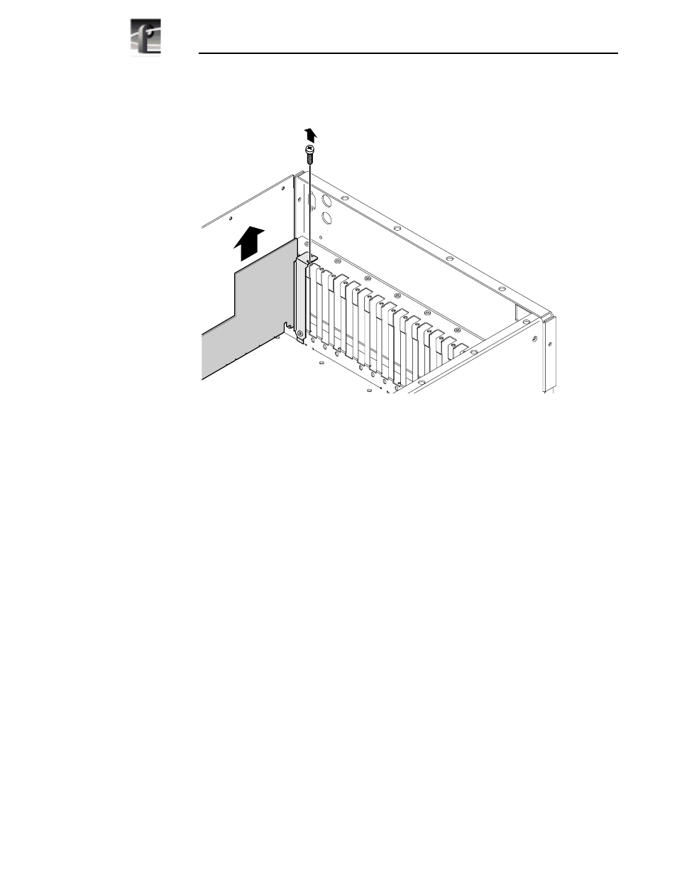
Figure 11. Location of circuit board mounting screw
c. If the VGA monitor cable is connected to the board, disconnect it now.
NOTE: See “General Installation Instructions” on page 17 for
proper circuit board handling warnings.
d. Carefully grasp the board and lift upward to free the circuit board from the
motherboard connectors. In some cases, it may be necessary to remove the
board in the adjacent slot J3 before removing the VGA-I/O board.
e. Verify your VGA-I/O board switch settings match Figure 8 on page 35 for
the CEX595 board or Figure 9 on page 36 for the CEX585 board.
f. Reinstall the VGA-I/O board by aligning it with the connectors on the
motherboard and then pressing down firmly until the board is seated. The
board is properly seated when the top of the rear mounting bracket is
resting on the rear cabinet wall shelf.
g. Reinstall the circuit board mounting screw and then proceed to the next
section “Installing the Parallel Port L-bracket”.
9897-24