Audio i/o circuit board (optional, various slots f – Grass Valley PDR100 User Manual
Page 66
Chapter 3 Mechanical Installation
3-42
PDR100 Installation
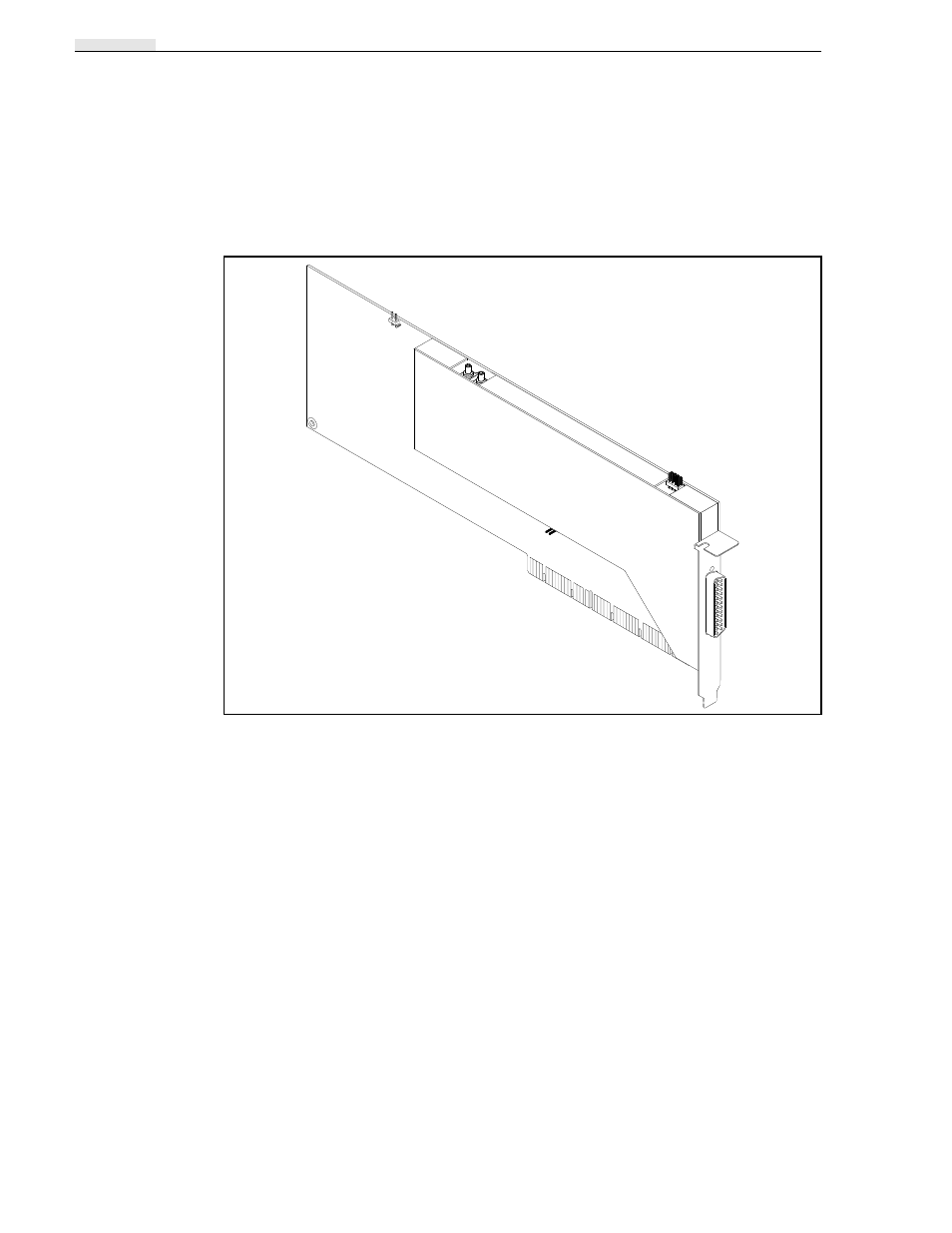
Audio I/O Circuit Board (Optional, Various Slots from J3-J13)
The Audio I/O circuit board is a purchased circuit card designed with an EISA- bus
interface for use in PC applications. In order to prevent the Processor reconfiguring
the board, a disable jumper, J4, is provided so that the processor will not recognize
the board and attempt to reconfigure it at boot-up. See Figure 3-39.
Figure 3-39. Audio I/O Circuit Board Showing Square-Pin Locations
The audio lines can be terminated for 600
Ω
impedance or high impedance (20 k
Ω
).
The impedance is determined by whether there are jumpers installed on the four sets
of pins (one for each channel) on the top of circuit board. When the pins are shorted
together by jumpers, the lines are terminated in 600
Ω
. The PDR100 is normally
shipped with jumpers installed for 600
Ω
termination.
J4
Plug jumper installed on
J4 keeps the Processor from
attempting to reconfigure at
boot-up.
CHA
CHB
CHC
CHD
Play
Record
Clock Inputs